Ethernet/IP Object Model
In EtherNet/IP networks, In-Sight vision systems act as servers, with support for both explicit and implicit I/O messaging. For example, you can transfer data from inspections to clients using explicit messages or through implicit connections. You can also use implicit connections to control acquisitions, triggers, and spreadsheet events.
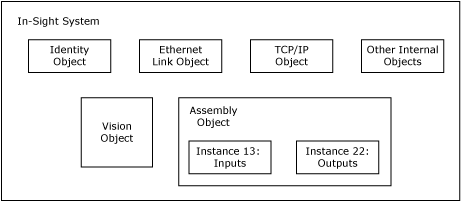
The Identity Object, Ethernet Link Object, TCP/IP Object and the Other Internal Objects are required by the EtherNet/IP specification. The different instances of the Assembly Object are used to exchange application data with EtherNet/IP clients. The Vision Object is defined by the In-Sight vision system to provide information specific to In-Sight vision systems. The current object model provided by In-Sight vision systems is illustrated in the following figure:
-
Assembly Object: The Assembly Object binds attributes of multiple objects, which allows data to and from each object to be sent or received over a single connection. Assembly Objects can be used to bind input data or output data. The terms "input" and "output" are defined from the point of view of the network. Input produces data on the network, and output consumes data from the network.
-
Identity Object: The Identity Object provides identification and general information for the device.
-
Ethernet Link Object:The Ethernet Link Object maintains link-specific counters and status information for an Ethernet 802.3 communications interface.
-
TCP/IP Object: The TCP/IP Object provides a mechanism to query and possibly configure the TCP/IP network interface configuration of a device. Examples of items of interest include the IP Address, Network Mask, and Gateway Address of a device.
-
Vision Object: The Vision Object contains all of the services and attributes specific to In-Sight vision systems. This includes acquisition, inspection, job switching, and communications with the In-Sight Spreadsheet.
The I/O Assembly data attribute for the input and output data has the following formats:
| Input Assembly Instance | Output Assembly Instance |
|---|---|
|
13 Note: For more information, see EtherNet/IP Input Assembly - Instance 13
|
22 Note: For more information, see EtherNet/IP Output Assembly - Instance 22
|
-
If using an EDS generated profile, the EDS generated profile only allows a connection of up to 496 bytes, even though the maximum size of the Input Assembly is 500 bytes.
-
When using Rockwell RSLogix Studio 5000 version 21 through 25, the default Input and Output Assembly sizes for the In-Sight generated profile (496 bytes) cannot be edited, and default to the largest Input and Output Assembly sizes.
-
The Acquisition ID increments at the beginning of acquisition, when the Trigger Ack is generated and sent to the PLC. The Inspection ID increments when the Inspection Completed bit toggles, at which time the Results Valid bit is set to High, and the Inspecting bit is set to Low.