Inputs/Outputs
The Inputs/Outputs application step allows you to configure the signals on the input and output data lines of your vision system.
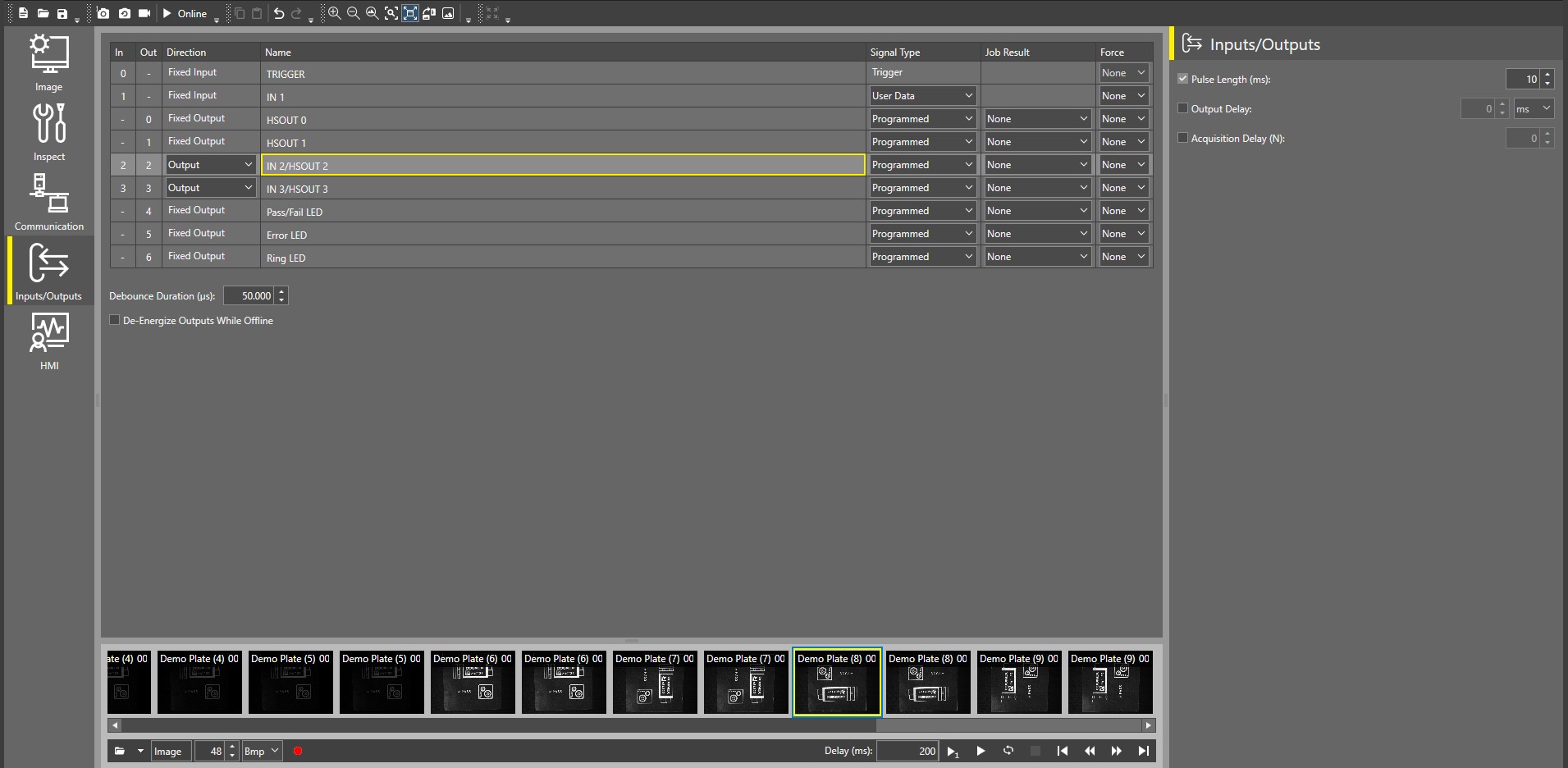
Use the data line table to configure each input/output line. Select a row in the table to display additional settings for output lines on the right.
Debounce Duration (µs) specifies the amount of time for all input lines in microseconds by which the device delays the recognition of a valid input signal. This does not apply to the TRIGGER line.
Check the De-Energize Outputs While Offline checkbox to de-energize the outputs when the vision system is Offline.
You can configure the following input and output lines for the In-Sight 2800 Vision System:
- IN 0 - fixed TRIGGER input line
- IN 1 - fixed configurable input line
- HSOUT 0 - fixed configurable output line
- HSOUT 1 - fixed configurable output line
- IN 2/HSOUT 2 - configurable input/output line
- IN 3/HSOUT 3 - configurable input/output line
- Pass/Fail LED - fixed configurable output line for the Pass/Fail LED
- Error LED - fixed configurable output line for the Error LED
You cannot modify the settings for IN 0, as IN 0 is a fixed TRIGGER input line. You can only configure the following input lines:
- IN 1
- IN 2/HSOUT 2
- IN 3/HSOUT 3
- If you want to use the IN 2/HSOUT 2 or IN 3/HSOUT 3 line as an input line, open the dropdown in the Direction column for the line you are configuring, and select Input.
-
In the Signal Type column of the line you are configuring, open the dropdown and select a signal type:
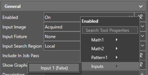
Signal Type Description User Data General purpose input line. You can use tool property linking to link the input signal to any boolean value in a tool.
For example, if you want to enable or disable a Find Pattern tool in your job using an input line, set your input line to User Data. Then, in the advanced tool settings view for the Find Pattern tool, open the tool property linking dropdown next to Enabled, and select your input line from the Inputs category:
Event Reserved for future use. Parallel Job Load To load jobs using the Job ID signal type on another input line, use the Parallel Job Load signal type. When a Parallel Job Load input line is HIGH (1), the device loads the job defined by the Job ID input lines. Job ID Use the Job ID signal type if you have another input line set up for Parallel Job Load.
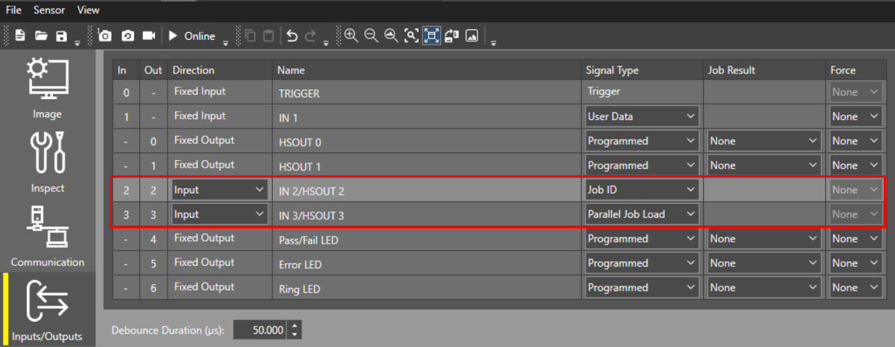
The Job ID input line can either be LOW (0) or HIGH (1), and defines the job file using a binary matrix. You can combine multiple Job ID input lines with a Parallel Job Load line to increase the number of jobs that you can potentially load.
Online Use the Online signal type to force the vision system Offline or Online (0 = Offline, 1 = Online). You can only use the Online signal type on one input line at a time. -
In the Force column, you can override your configured line settings for testing or debugging purposes, and force the input line ON (1) or OFF (0):
Force Description None The input line uses the configured line settings. On The input line is ON (1). Off The input line is OFF (0).
- To use the IN 2/HSOUT 2 or IN 3/HSOUT 3 line as an output line, open the dropdown in the Direction column, and select Ouput.
-
In the Signal Type column for the line you are configuring, open the dropdown and select a signal type:
Signal Type Description Programmed Transmits the Job Results defined in the Job Result settings for the output line. Either pulsed or steady-state. High Forces the output to HIGH (1). Low Forces the output to LOW (0). Acquisition Start Transmits a signal when a vision system acquisition starts. Always pulsed. Acquisition End Transmits a signal when a vision system acquisition is complete. Always pulsed. Acquisition Missed Transmits a signal if the vision system receives a trigger signal and cannot run the acquisition, or when a new acquisition starts if no image buffer is available. Always pulsed. Strobe Uses the rising or falling edge of the signal to trigger a strobe. You can set the starting point of the signal to trigger the light at the start of the image acquisition, or if the light needs precharge time, when receiving the trigger input. You can set trigger to acquisition delay in the Advanced Image settings. Job Completed Transmits a signal when a job is complete. Always pulsed. Online HIGH (1) when the vision system is Online, LOW (0) when the vision system is Offline. Busy HIGH (1) when the vision system is running a job or responding to user input, LOW (0) when the vision system is idle. Job Load OK Transmits a signal when a job loads successfully. Always pulsed. Job Load Fail Transmits a signal when a job fails to load. Always pulsed. -
Selecting the Programmed signal type enables the Job Result setting, allowing you to send tool property values from your job result on the output line.
In the Job Result column for the line you are configuring, open the dropdown and select the tool property you want the output line to use.
You can add cell values from the Math tool into your output lines as cell values are tool properties of the Math tool.
Note: The Pass/Fail LED and Error LED lines can only accept tool properties with boolean values as a Job Result. -
In the Force column, you can override your configured line settings for testing or debugging purposes, and force the output line ON (1) or OFF (0):
Force Description None The output line uses the configured line settings. On The output line is ON (1). Off The output line is OFF (0). -
On the right side of the screen next to the data line settings table, adjust the Pulse Length (ms) parameter to change the length of a pulse on the selected line.
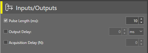
- To enable output delay, check the Output Delay checkbox and define the delay in ms. The output delay counts from the moment the vision system receives the trigger. For example, if you set Output delay to 100 ms and your overall job time is 80 ms, the output delay is 20 ms.
Note: PLC always receives the Output signal in exactly 100 ms after the trigger signal.
-
If you are configuring the Pass/Fail LED line, you can also change the colors that the LED uses by opening the Tri-color LED dropdown, and selecting one of the following options:
- Off/Green
- Off/Red
- Red/Green
Note: If you select the Red/Green option, the pulse function automatically gets disabled for the Pass/Fail LED and the illuminator LEDs. The pulse option is available if you choose Off/Green or Off/Red.
To load a job through discrete inputs, you have to set one of the inputs to Parallel Job Load and one or more Inputs to Job ID.
The Job ID lines are based on binary numbers. One single line set to Job ID can represent the values consisting of 0 or 1. Multiple lines set to Job ID can represent more values based on the binary number system. For example, 000=0, 011=3, 101=5. The In-SightVision System translates the binary value into a decimal value which you can use to load a job. See the table below showing decimal to binary conversion:
| Decimal | Binary |
|---|---|
| 0 | 0 |
| 1 | 1 |
| 2 | 10 |
| 3 | 11 |
| 4 | 100 |
| 5 | 101 |
| 6 | 110 |
| 7 | 111 |
The following example shows how to to load a job through Inputs/Outputs:
-
The example below represents three available inputs. Set Input 1 to Parallel Job Load and Input 2 and Input 3 to Job ID.
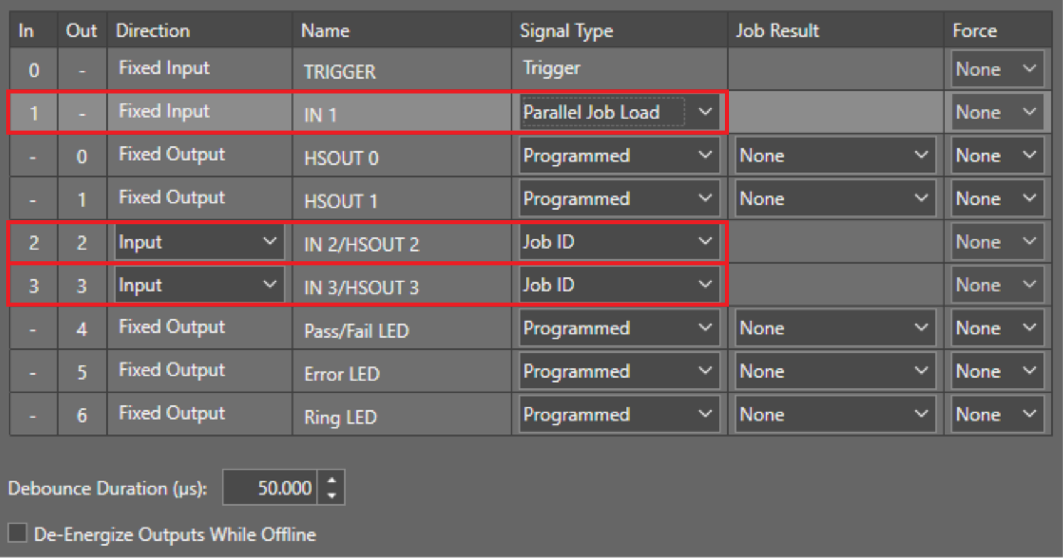 Note: The Job ID bit is a binary coded number. The lowest line number is the least significant bit (LSB). Job ID lines must be next to each other.
 - To load the job Test.jobx by discrete inputs you have to save the job with a numerical prefix on the camera. For example, to load a job by the binary number “11” you have to save the job as 3Test.jobx.
-
Based on the image above, to load 3Test.jobx, set the camera Inputs 2 and 3 to high by your PLC and keep them high. Then set the Input 1 Parallel Job Load to high to read the Job ID Inputs and load the job.
- Now you can set all Job ID and Job Load Inputs back to low.