Trigger and Laser Enable Wiring
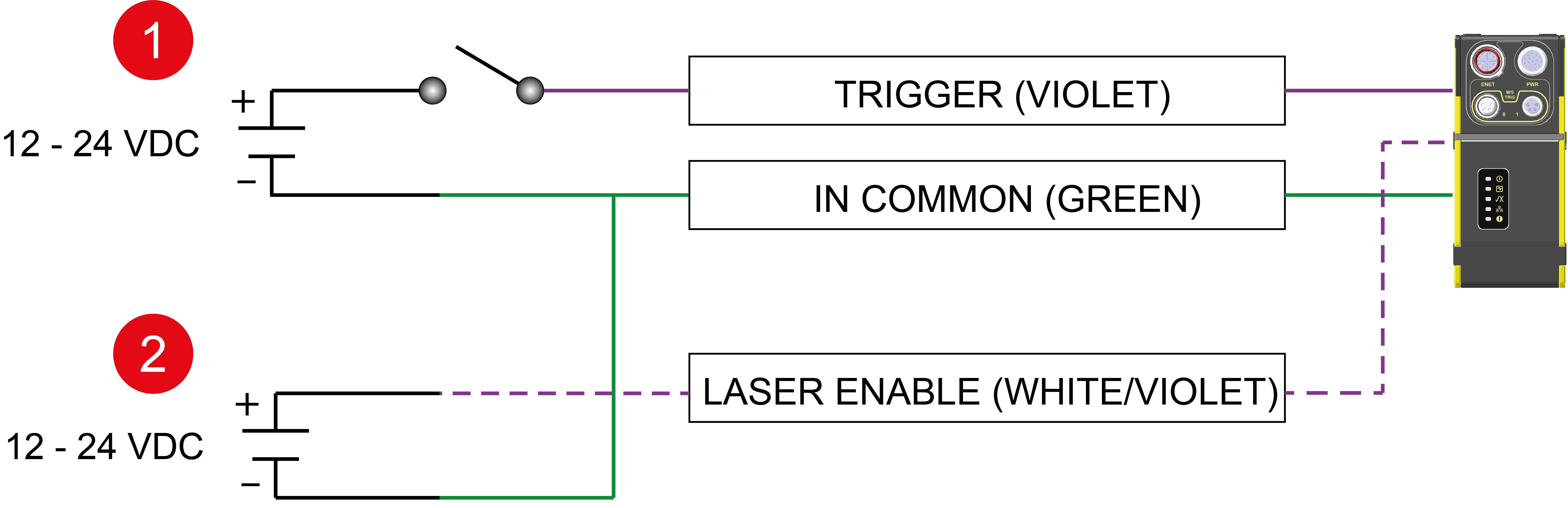
The following table presents the wiring schematic of the trigger and the laser in NPN configuration:
|
|
|---|---|
| Number | Component |
|
1 |
Trigger (Sensor Sinks Current - NPN) |
|
2 |
Laser Enable (Sensor Sinks Current - NPN) |
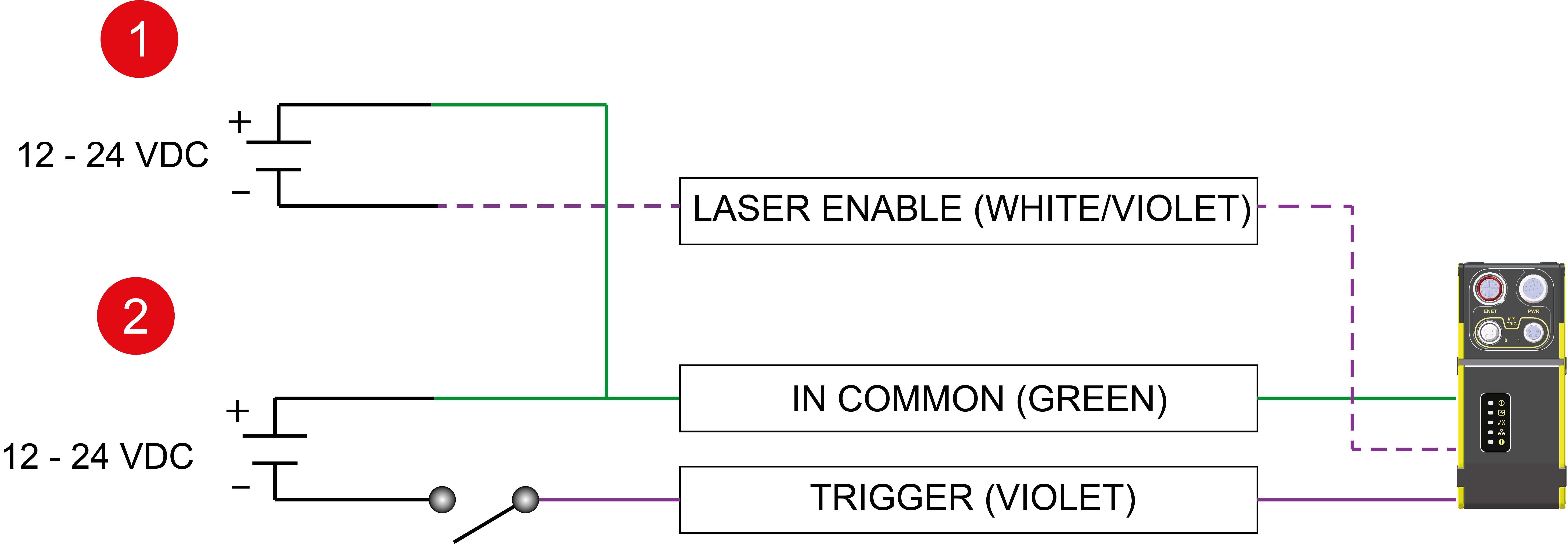
The following table presents the wiring schematic of the trigger and the laser in PNP configuration:
|
|
|---|---|
| Number | Component |
|
1 |
Laser Enable (Sensor Sources Current- PNP) |
|
2 |
Trigger (Sensor Sources Current - PNP) |