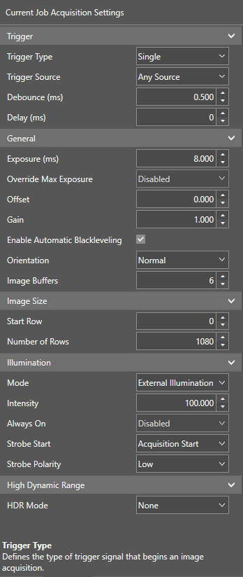
Acquisition Panel
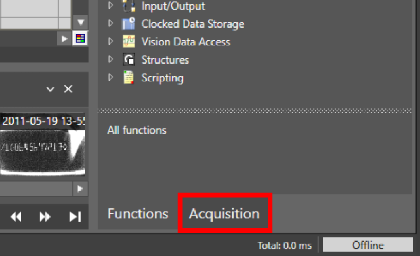
On the Acquisition Acquisition is the process or result of the vision system acquiring a new image. panel, you can adjust various settings for the next image acquisition. To open the acquisition panel, click on Acquisition in the bottom right corner.
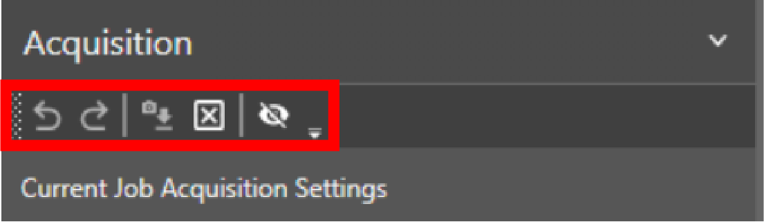
Acquisition action bar elements:
|
|
||
|---|---|---|
| Icon | Name | Action |
|
|
Undo | Undo last action. |
|
|
Redo | Redo last action. |
|
|
Reset Setting | Resets the settings back to the property values in-use when you first connected to the device. |
|
|
Resets Acquisition | Resets acquisition settings to the default values. |
|
|
Show/hide no effect settings | Toggles the visibility of settings that currently have no effect. |


Acquisition settings:
|
|
|||||||||||||||||||||||||||||||||||||||||||||||||||||||||||||||||||||||||||||||||||||||||||||||||||||||||||||||||||||||||||||||||||||||||||
|---|---|---|---|---|---|---|---|---|---|---|---|---|---|---|---|---|---|---|---|---|---|---|---|---|---|---|---|---|---|---|---|---|---|---|---|---|---|---|---|---|---|---|---|---|---|---|---|---|---|---|---|---|---|---|---|---|---|---|---|---|---|---|---|---|---|---|---|---|---|---|---|---|---|---|---|---|---|---|---|---|---|---|---|---|---|---|---|---|---|---|---|---|---|---|---|---|---|---|---|---|---|---|---|---|---|---|---|---|---|---|---|---|---|---|---|---|---|---|---|---|---|---|---|---|---|---|---|---|---|---|---|---|---|---|---|---|---|---|---|
| Section | Setting | Description | Values | ||||||||||||||||||||||||||||||||||||||||||||||||||||||||||||||||||||||||||||||||||||||||||||||||||||||||||||||||||||||||||||||||||||||||
| Trigger | Trigger Type | Defines the type of trigger signal that begins an image acquisition. | Single: An external trigger event triggers the start of an acquisition and an inspection. | ||||||||||||||||||||||||||||||||||||||||||||||||||||||||||||||||||||||||||||||||||||||||||||||||||||||||||||||||||||||||||||||||||||||||
|
Self: Acquisitions and inspections occur periodically. |
|||||||||||||||||||||||||||||||||||||||||||||||||||||||||||||||||||||||||||||||||||||||||||||||||||||||||||||||||||||||||||||||||||||||||||
|
Trigger Interval (ms) Appears in Self Trigger mode only. |
Defines the time in milliseconds between acquisitions, when Self trigger type is selected. | [0, 10000] | |||||||||||||||||||||||||||||||||||||||||||||||||||||||||||||||||||||||||||||||||||||||||||||||||||||||||||||||||||||||||||||||||||||||||
|
Trigger Source (ms) Appears in Self Trigger mode only. |
Defines the trigger source for the acquisition: |
Trigger Input Line: Trigger acquisition when the trigger input of the vision system line goes high. | |||||||||||||||||||||||||||||||||||||||||||||||||||||||||||||||||||||||||||||||||||||||||||||||||||||||||||||||||||||||||||||||||||||||||
| Camera Trigger Button: Trigger acquisition by pressing the trigger button on the vision system. | |||||||||||||||||||||||||||||||||||||||||||||||||||||||||||||||||||||||||||||||||||||||||||||||||||||||||||||||||||||||||||||||||||||||||||
| Native Mode: Trigger acquisition by sending a Native Mode command to the vision system. | |||||||||||||||||||||||||||||||||||||||||||||||||||||||||||||||||||||||||||||||||||||||||||||||||||||||||||||||||||||||||||||||||||||||||||
| Network (UDP): Trigger acquisition when the vision system receives a specifically formatted UPD package. | |||||||||||||||||||||||||||||||||||||||||||||||||||||||||||||||||||||||||||||||||||||||||||||||||||||||||||||||||||||||||||||||||||||||||||
| Factory Protocols: Trigger acquisition by toggling a bit with the configured industrial protocol. | |||||||||||||||||||||||||||||||||||||||||||||||||||||||||||||||||||||||||||||||||||||||||||||||||||||||||||||||||||||||||||||||||||||||||||
| WebHMI The operator interface through which the operator interacts with the vision system. Trigger Button: Trigger acquisition by pressing the trigger button in the WebHMI. | |||||||||||||||||||||||||||||||||||||||||||||||||||||||||||||||||||||||||||||||||||||||||||||||||||||||||||||||||||||||||||||||||||||||||||
|
Debounce (ms) Appears in Single Trigger mode only. |
Defines the time in milliseconds that a camera trigger has to last to a trigger an acquisition. | [0, 10] | |||||||||||||||||||||||||||||||||||||||||||||||||||||||||||||||||||||||||||||||||||||||||||||||||||||||||||||||||||||||||||||||||||||||||
|
Delay (ms) Appears in Single Trigger mode only. |
Defines the delay between the time that the vision system receives a trigger to acquire an image, and the time the vision system begins the image acquisition. | [0,10000] | |||||||||||||||||||||||||||||||||||||||||||||||||||||||||||||||||||||||||||||||||||||||||||||||||||||||||||||||||||||||||||||||||||||||||
| General | Exposure (ms) |
Defines the exposure time. When the vision system receives an image acquisition trigger signal, light is integrated into the image sensor array for the specified duration. Note: The maximum exposure value varies based on the capabilities of the connected illumination.
|
[0, 6.5] | ||||||||||||||||||||||||||||||||||||||||||||||||||||||||||||||||||||||||||||||||||||||||||||||||||||||||||||||||||||||||||||||||||||||||
| Override Max Exposure |
Allows setting the exposure time to values greater than the recommended maximum. Note: When enabled, if the exposure time exceeds the capability of the illumination accessory, the illumination accessory will not remain on during the entire exposure.
|
[Enabled, Disabled] | |||||||||||||||||||||||||||||||||||||||||||||||||||||||||||||||||||||||||||||||||||||||||||||||||||||||||||||||||||||||||||||||||||||||||
| Offset |
Brightens the image additively. Enhances dark areas but loses detail on bright spots. Most useful when combined with Gain. |
[0, 255] | |||||||||||||||||||||||||||||||||||||||||||||||||||||||||||||||||||||||||||||||||||||||||||||||||||||||||||||||||||||||||||||||||||||||||
| Gain | Brightens the image multiplicatively. Enhances dark areas but loses detail on bright spots, and increases image noise. Most useful when combined with Offset. | [1x, 2x, 3x, 4x, 6x, 8x] | |||||||||||||||||||||||||||||||||||||||||||||||||||||||||||||||||||||||||||||||||||||||||||||||||||||||||||||||||||||||||||||||||||||||||
| Orientation | Defines the orientation at which In-Sight processes the acquired image. | [Normal, Mirrored horizontally, Flipped vertically, Rotated 180 degrees] | |||||||||||||||||||||||||||||||||||||||||||||||||||||||||||||||||||||||||||||||||||||||||||||||||||||||||||||||||||||||||||||||||||||||||
| Image Buffers |
Defines the number of image buffers allocated for acquisition. Considerations for setting the image buffer:
Note: When in Single Trigger mode, if a trigger is received but no buffer is available for image acquisition, the image acquisition does not occur. In addition, if a Discrete Output line is configured to use ERR: Missed Acquisition, this signal is raised for each acquisition until a buffer becomes available.
|
[6, 25] | |||||||||||||||||||||||||||||||||||||||||||||||||||||||||||||||||||||||||||||||||||||||||||||||||||||||||||||||||||||||||||||||||||||||||
|
Line Scan Note: The Line Scan option is only available for IS3800 Line Scan models
|
Line Trigger Type | Defines the type of encoder. | Software Encoder: The software encoder emulates a hardware encoder and acquires lines at a rate defined by the Line Period parameter. | ||||||||||||||||||||||||||||||||||||||||||||||||||||||||||||||||||||||||||||||||||||||||||||||||||||||||||||||||||||||||||||||||||||||||
|
Hardware Encoder: An external hardware encoder drives the line triggers at the resolution defined by the Steps Per Line parameter. |
|||||||||||||||||||||||||||||||||||||||||||||||||||||||||||||||||||||||||||||||||||||||||||||||||||||||||||||||||||||||||||||||||||||||||||
| Line Period |
Defines the time for each image line in microseconds. Note: The Line Period parameter is only available when the Line Trigger Type is set to Software Encoder.
Note: If you select a value that exceeds the maximum line period for a given exposure, the line period is automatically set to the fastest possible value.
Cognex recommends the following line period settings to avoid line overrun, depending on the resolution mode:
|
[0, 1000000] |
|||||||||||||||||||||||||||||||||||||||||||||||||||||||||||||||||||||||||||||||||||||||||||||||||||||||||||||||||||||||||||||||||||||||||
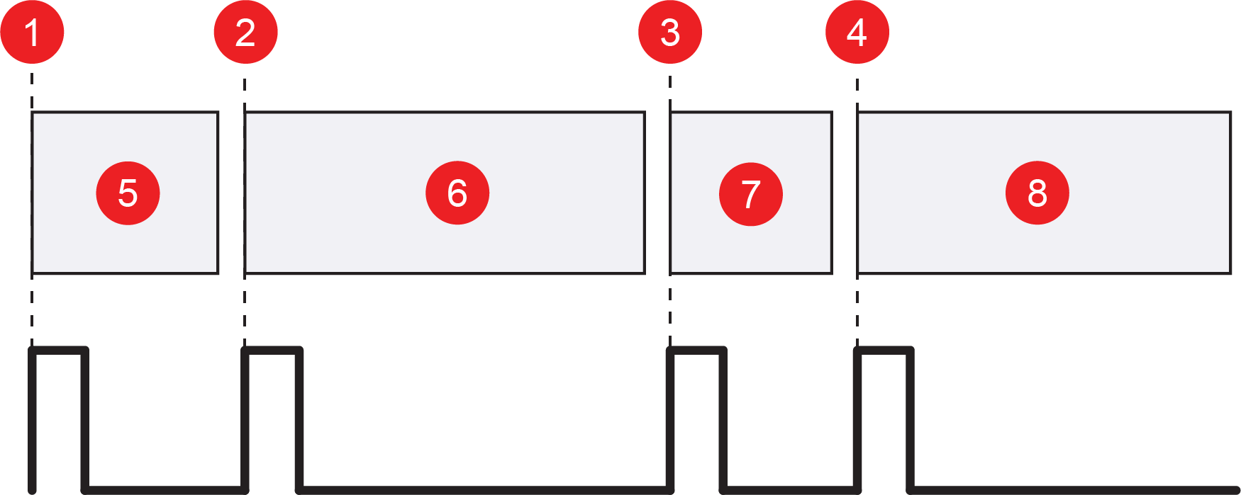
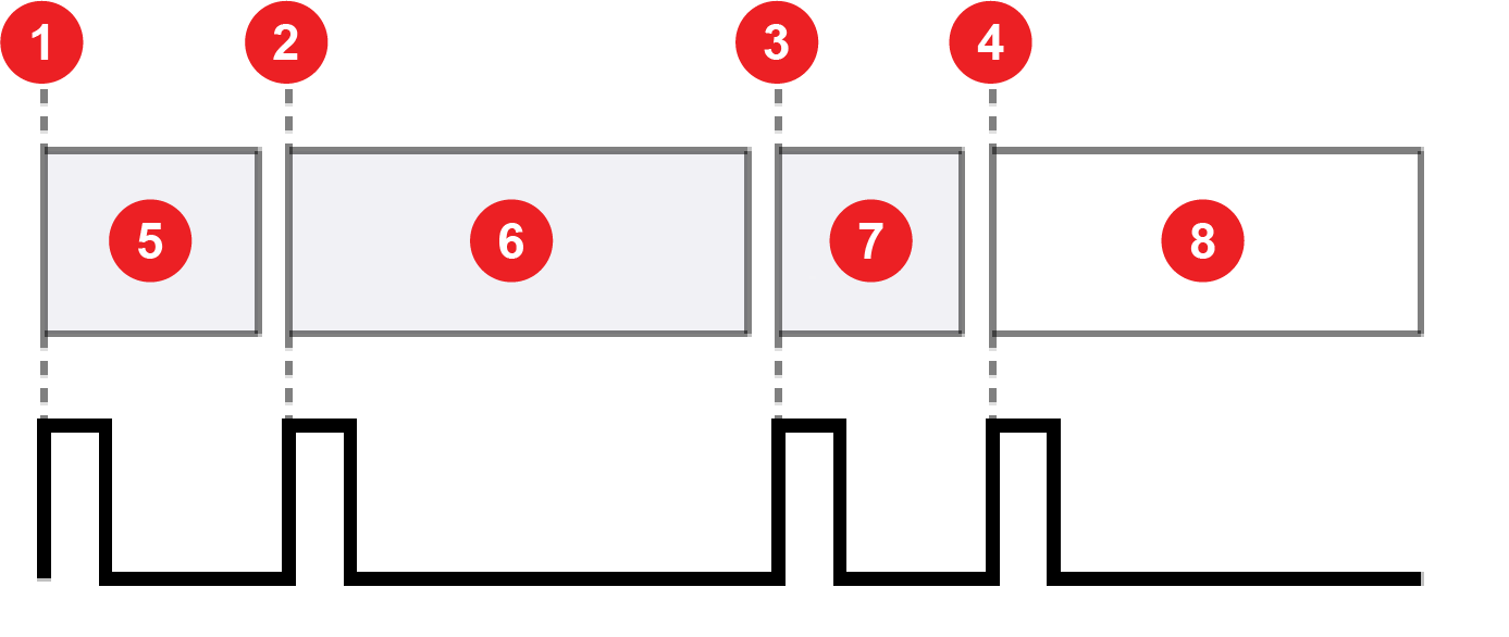
| Steps Per Line |
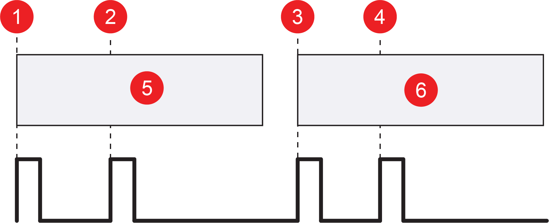
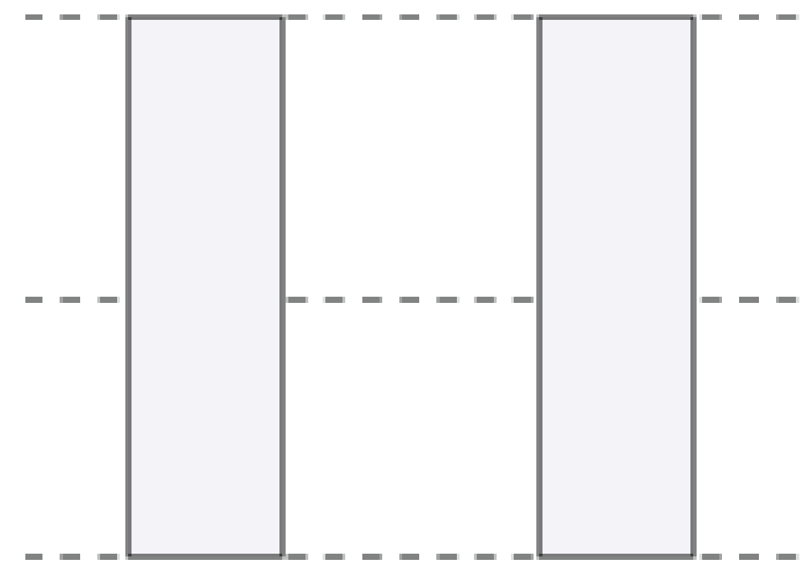
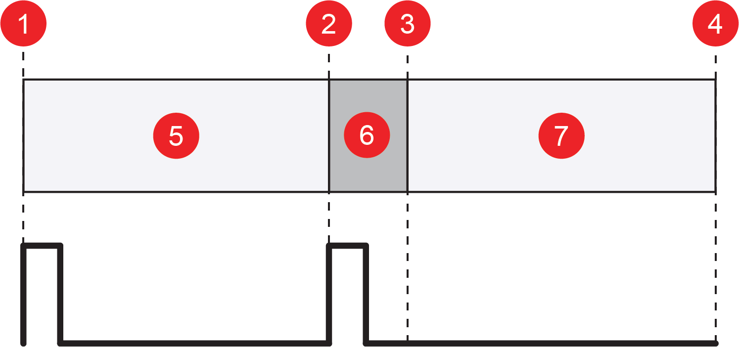
Defines the number of encoder steps for each image line. A step is a complete cycle of the encoder signal or signals, depending on the encoder you use. For a single-line hardware encoder, a complete cycle is equivalent to two signal transitions. For a quadrature hardware encoder, a complete cycle is equivalent to four signal transitions. The following image shows how steps per line correlate to signal transition for different encoders:
Note: The Steps Per Line parameter is only available when the Line Trigger Type is set to Hardware Encoder.
|
[0.25, 4000000] Note: Increment by 0.5 for single-line hardware encoders, and by 0.25 for quadrature hardware encoders.
|
|||||||||||||||||||||||||||||||||||||||||||||||||||||||||||||||||||||||||||||||||||||||||||||||||||||||||||||||||||||||||||||||||||||||||
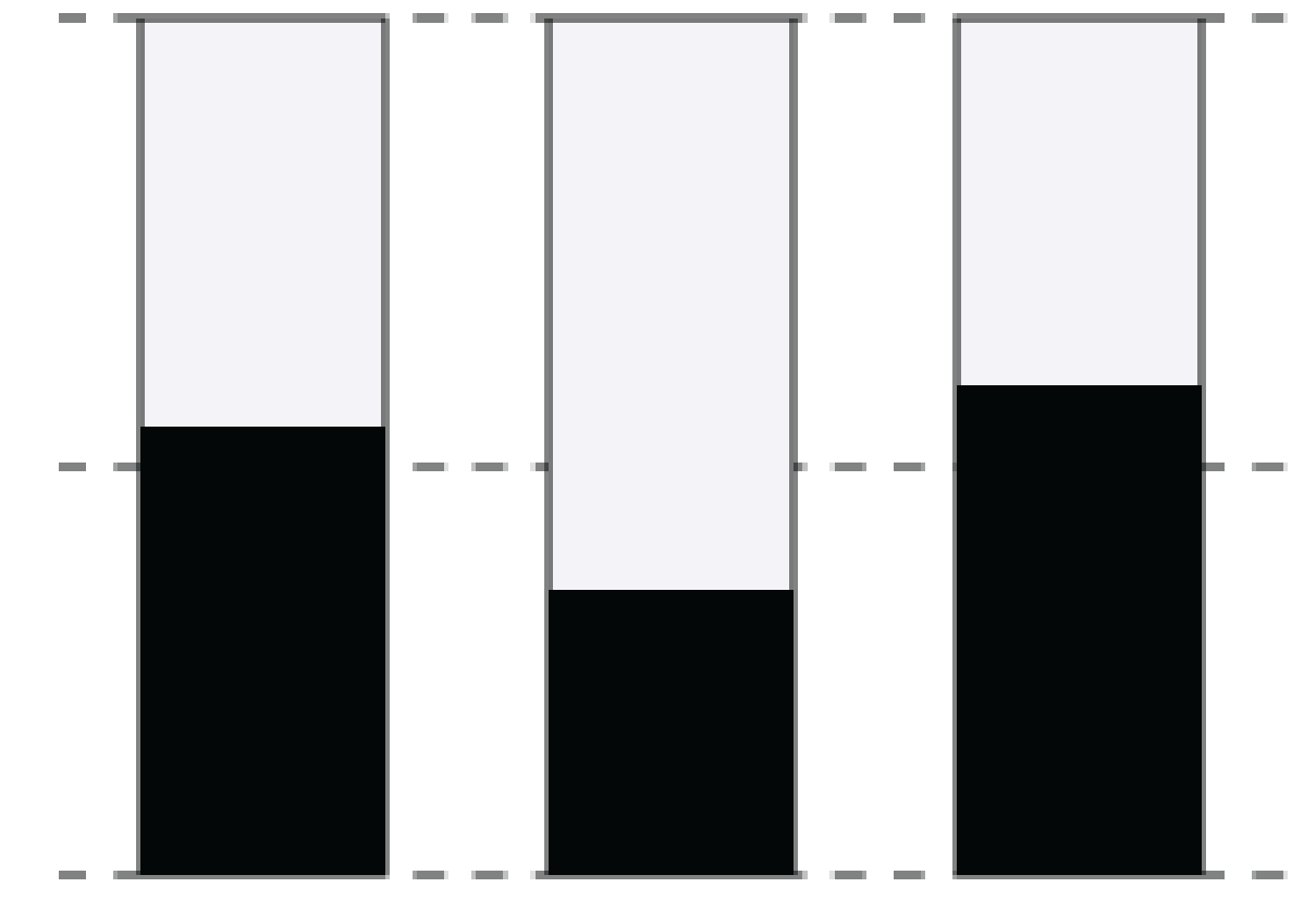
| Encoder Type | Defines the type of hardware encoder used to trigger line acquisitions. | Single (default): when using a single-line encoder, you must wire it to the first encoder input. Connecting the line to the second input has no effect. | |||||||||||||||||||||||||||||||||||||||||||||||||||||||||||||||||||||||||||||||||||||||||||||||||||||||||||||||||||||||||||||||||||||||||
| Quadrature: Quadrature encoders provide direction information and require two high-speed inputs. | |||||||||||||||||||||||||||||||||||||||||||||||||||||||||||||||||||||||||||||||||||||||||||||||||||||||||||||||||||||||||||||||||||||||||||
| Direction |
Defines the forward direction of the quadrature encoder. The vision system uses the Direction to determine the correct operating direction. Reversing the direction during image acquisition stops the acquisition. You can continue the acquisition when the vision system reaches the saturation boundary by advancing forward back to the original position. Note: The Direction parameter is only available when the Encoder Type is set to Quadrature.
|
Positive (default): Positive direction indicates a part moving from right to left, from the perspective of the vision system. | |||||||||||||||||||||||||||||||||||||||||||||||||||||||||||||||||||||||||||||||||||||||||||||||||||||||||||||||||||||||||||||||||||||||||
| Negative | |||||||||||||||||||||||||||||||||||||||||||||||||||||||||||||||||||||||||||||||||||||||||||||||||||||||||||||||||||||||||||||||||||||||||||
| Clip Mode |
Specifies an action if an image acquisition trigger is received, but the specified number of lines have not yet been acquired.
|
[No Clipping, Overlap, Fill Black] | |||||||||||||||||||||||||||||||||||||||||||||||||||||||||||||||||||||||||||||||||||||||||||||||||||||||||||||||||||||||||||||||||||||||||
| Acquisition Duration |
Specifies when to end image acquisition if the Clip Mode is set to Fill Black or Reduce Image.
Note: The End of Trigger mode can only be used with the Reduce Image clip mode.
|
||||||||||||||||||||||||||||||||||||||||||||||||||||||||||||||||||||||||||||||||||||||||||||||||||||||||||||||||||||||||||||||||||||||||||
| Encoder Trigger Delay | Specifies a delay to the trigger in encoder steps. Up to 18 triggers can be queued within the delay. | ||||||||||||||||||||||||||||||||||||||||||||||||||||||||||||||||||||||||||||||||||||||||||||||||||||||||||||||||||||||||||||||||||||||||||
| Encoder Acquisition Timeout | Defines the maximum amount of time to acquire an image in milliseconds. If the vision system does not complete image acquisition within the specified time, the vision system aborts the acquisition and an issues Acquisition Error. |
[0, 10000] Default: 0, timeout disabled. |
|||||||||||||||||||||||||||||||||||||||||||||||||||||||||||||||||||||||||||||||||||||||||||||||||||||||||||||||||||||||||||||||||||||||||
| Image size | Start Row | Defines the first row to transfer from the image sensor into the memory of the vision system. |
[0, 1079] Note: For IS2800, ADV182, and IS3800 models, values must be divisible by 4.
|
||||||||||||||||||||||||||||||||||||||||||||||||||||||||||||||||||||||||||||||||||||||||||||||||||||||||||||||||||||||||||||||||||||||||
| Number of Rows | Defines the number of image sensor rows to transfer into the memory of the vision system. |
[1, 1080] Note: For IS2800, ADV182, and IS3800 models, values must be divisible by 4.
|
|||||||||||||||||||||||||||||||||||||||||||||||||||||||||||||||||||||||||||||||||||||||||||||||||||||||||||||||||||||||||||||||||||||||||
| Number of Rows (Line Scan) |
Defines the number of lines to acquire to create the full line scan image. Note: If you choose a smaller frame length option in the Camera Configuration utility, the maximum number of rows decreases accordingly.
|
[8, 16376] Note: You can only adjust the value by increments of 12 rows.
|
|||||||||||||||||||||||||||||||||||||||||||||||||||||||||||||||||||||||||||||||||||||||||||||||||||||||||||||||||||||||||||||||||||||||||
| Illumination | Mode | Defines the illumination device. | [Disabled, Integrated Illumination, External Illumination] | ||||||||||||||||||||||||||||||||||||||||||||||||||||||||||||||||||||||||||||||||||||||||||||||||||||||||||||||||||||||||||||||||||||||||
| Intensity | Specifies the intensity of the illumination device. | [0, 100] | |||||||||||||||||||||||||||||||||||||||||||||||||||||||||||||||||||||||||||||||||||||||||||||||||||||||||||||||||||||||||||||||||||||||||
| Always On | When enabled, the illumination device is on continuously. | [Disabled, Enabled] | |||||||||||||||||||||||||||||||||||||||||||||||||||||||||||||||||||||||||||||||||||||||||||||||||||||||||||||||||||||||||||||||||||||||||
| Strobe Start Appears in External Illumination mode only. | Defines when the strobe fires. | [Camera Trigger, Acquisition Start] | |||||||||||||||||||||||||||||||||||||||||||||||||||||||||||||||||||||||||||||||||||||||||||||||||||||||||||||||||||||||||||||||||||||||||
| Strobe Polarity
Appears in External Illumination mode only. |
Defines the signal that fires a connected strobe. | [Low, High] | |||||||||||||||||||||||||||||||||||||||||||||||||||||||||||||||||||||||||||||||||||||||||||||||||||||||||||||||||||||||||||||||||||||||||
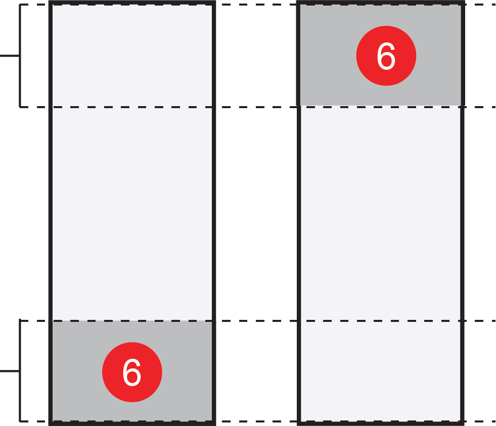
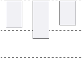
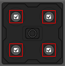
| Banks Enabled Appears in Integrated Illumination mode only. |
Check or uncheck the checkboxes inside the banks on the graphic to enable or disable each bank. Note: Banks graphics can vary depending on the illumination hardware attached to the vision system.
|
|
|||||||||||||||||||||||||||||||||||||||||||||||||||||||||||||||||||||||||||||||||||||||||||||||||||||||||||||||||||||||||||||||||||||||||
| Light Color Appears in Integrated Illumination mode only. | Defines the color of the illumination. | [WHITE, RED, GREEN, BLUE] | |||||||||||||||||||||||||||||||||||||||||||||||||||||||||||||||||||||||||||||||||||||||||||||||||||||||||||||||||||||||||||||||||||||||||
|
Focus Note: Focus options appear only when a liquid lens is attached to the vision system.
|
Focus Distance (mm) | Focus distance in millimeters. | [65, 4043] | ||||||||||||||||||||||||||||||||||||||||||||||||||||||||||||||||||||||||||||||||||||||||||||||||||||||||||||||||||||||||||||||||||||||||
| Focus Region | Defines the size and position of lens focus region. Click on the Edit button to set. | ||||||||||||||||||||||||||||||||||||||||||||||||||||||||||||||||||||||||||||||||||||||||||||||||||||||||||||||||||||||||||||||||||||||||||
| Autofocus | A single button to auto-set the focus position based on current settings. | ||||||||||||||||||||||||||||||||||||||||||||||||||||||||||||||||||||||||||||||||||||||||||||||||||||||||||||||||||||||||||||||||||||||||||
| High Dynamic Range | HDR Mode |
Enables or disables High Dynamic Range (HDR) processing. |
[None, HDR, HDR+] Note:
HDR+ is only available on IS3800 models. HDR is not available on color units.
|
||||||||||||||||||||||||||||||||||||||||||||||||||||||||||||||||||||||||||||||||||||||||||||||||||||||||||||||||||||||||||||||||||||||||