Encoder Inputs
The following image shows the encoder phase A and B inputs.
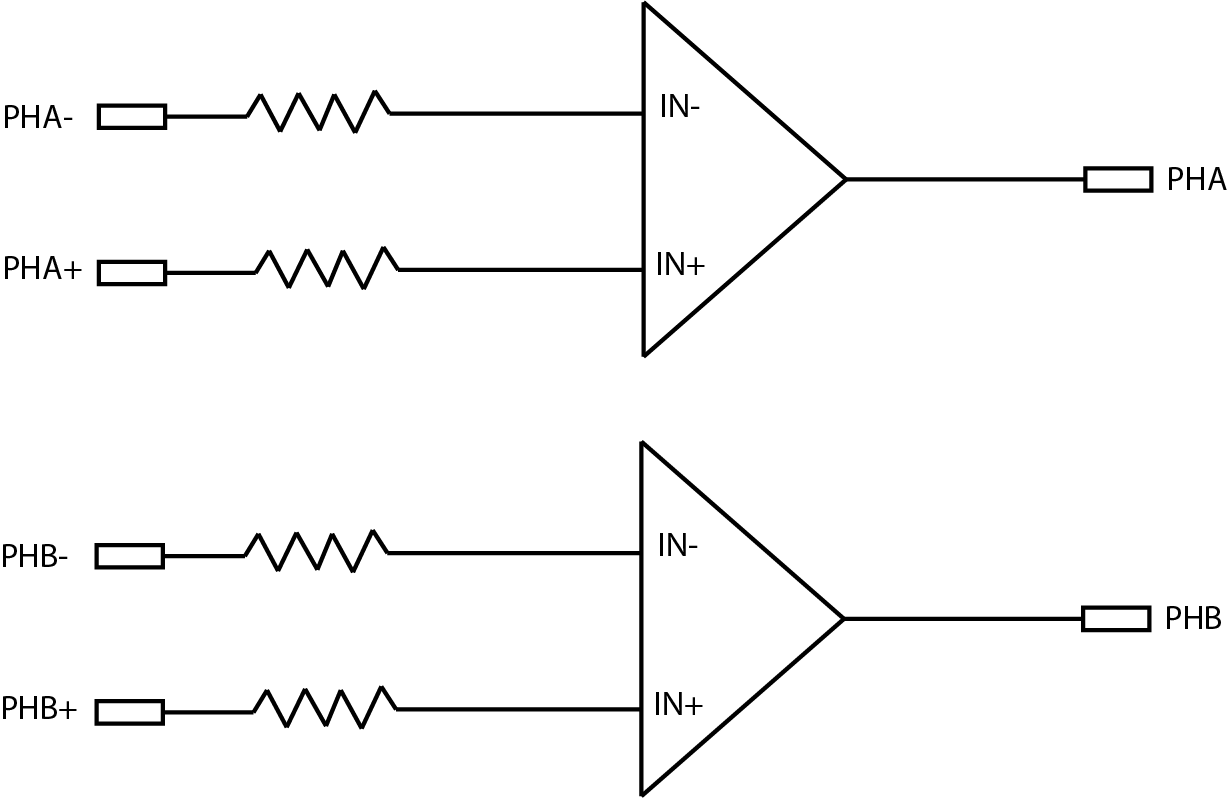
The encoder phase inputs can be driven with:
-
Differential decoder (5 V - 24 V)
-
Non-differential decoder (12 V - 24 V)
To create the required differential signal, you need a voltage divider when you use a non-differential decoder. See Encoder Wiring.
You can directly connect encoder drivers of RS-422 (±6 V) to the phase signals.
Input voltage requirements:
| Requirements | Minimum | Maximum |
| Differential voltage threshold | 4 V | 24 V |
| Voltage range with respect to power supply GND | 0 V | 24 V |
Note: If you are using a Single-Channel Encoder, always connect to the ‘PHA’ input.
WARNING: The frequency of pulses has to remain under 1000 kHz.
- Single-ended encoders use one wire each for signals A and B. Be aware single-ended encoders are susceptible to electrical noise. When using a single ended encoder, set the complementary differential inputs, A- and B-, to 1/2 of the encoder operating voltage (for example, 12 V for a 24 V encoder.) Use only 12 V or 24 V single ended encoders.
- Differential encoders use two lines each for signals A and B. Differential encoders greatly reduce susceptibility to electrical noise and they can be powered from 5 V to 24 V.