Create2dHeightMapFromPointCloud
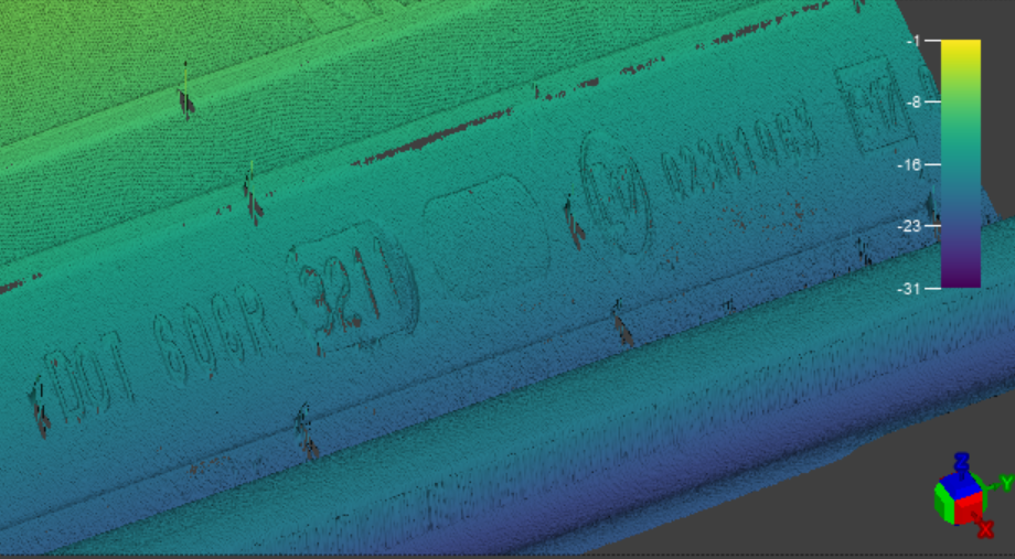
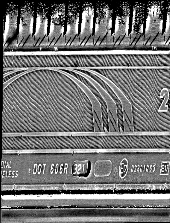
The Create2dHeightMapFromPointCloud function allows you to create a relative height map of all points within a Region of Interest (RoI) in the point cloud. The height map translates the relative height of each point in the RoI to a greyscale value between 0 and 255, allowing you to visualize the differences in height between the points. The function returns an Image structure containing a 2D height map image.
The Create2dHeightMapFromPointCloud function is particularly useful in OCR applications, as it is capable of clearly highlighting the small features of embossed or engraved characters.
|
|
|
| Input Point Cloud | Output Height Map |
The Create2dHeightMapFromPointCloud function has the following syntax:
Create2dHeightMapFromPointCloud(PointCloud,Fixture3D,ExternalFixture,Region3D,ExternalRegion,FeatureWidth,FeatureHeight,ProjectionMode,AutoAdjustBoxZRange,MatchInputResolution,RequestedPixelResolutionX,RequestedPixelResolutionY,DefaultMissingPixelHeight,Show)
| Parameter | Description | ||||||||||||||||||
|
PointCloud |
Reference to a cell containing a point cloud. The default value is $A$0. |
||||||||||||||||||
|
Fixture3D |
Specifies the point cloud coordinate system in which the 3D fixture is defined. It is offset from the PointCloud origin in the following format with the following arguments: {X, Y, Z, Rotation, Tilt, TiltDirection}
Note: The Fixture3D parameter is only available if you set External Fixture to 0.
|
||||||||||||||||||
| External Fixture |
Specifies a reference to a Fixture3D structure defined in another cell. The function uses the referenced cell as the fixture of the function. Set to 0 (OFF) to use the internal fixture of the function instead. |
||||||||||||||||||
| Match Grey Image Size | Match the height map image size to the greyscale image size. | ||||||||||||||||||
|
Box3D |
Specifies the dimensions, offset and angle for the 3D rectangle of the function. It is offset from the PointCloud origin in the following format with the following arguments: {SizeX, SizeY, X, Y, Z, Rotation, Tilt, TiltDirection}
Note: This parameter is available only if External Box is set to 0.
|
||||||||||||||||||
|
External Box |
Specifies a reference to a 3D region defined in another cell. The function uses the referenced cell as the Region of Interest of the function. Set to 0 (OFF) to use the internal Box3D structure of the function as the ROI. |
||||||||||||||||||
| Projection Mode |
Specifies the method of calculating the relative height of the points in the point cloud. The available values are the following:
|
||||||||||||||||||
|
Feature Width |
Specifies the expected width in millimeters of a typical feature of interest. The Feature Width parameter defines the resolution of the height map. Note: For OCR applications, the character stroke width defines the Feature Width setting. For example, if the character stroke is 1 mm, set the Feature Width to at least 0.25 mm in order to get good character resolution in the height map.
|
||||||||||||||||||
| Feature Height | Specifies the expected height in millimeters of a typical feature of interest. The Feature Height parameter defines the sensitivity of the height map. | ||||||||||||||||||
| Auto Adjust Box Z Range | Specifies whether to automatically adjust the Z range of the RoI box to start with the height of the lowest point. This setting only applies when using Bottom of Region as the value for Projection Mode. | ||||||||||||||||||
| Match Input Resolution | Specifies whether to match the height map pixel size to the native resolution of the point cloud. Enabling this setting disables the Requested Pixel Resolution X and Requested Pixel Resolution Y settings. | ||||||||||||||||||
| Requested Pixel Resolution X |
Specifies the number of pixels corresponding to the Feature Width value on the X axis. For example, if Feature Width is defined as 1 mm, and Requested Pixel Resolution X is defined as 5, then the output height map will have 5 pixels for 1 mm on the X axis. Note: If you change the value for Requested Pixel Resolution X, make sure to adjust the Requested Pixel Resolution Y parameter as well. Otherwise, the aspect ratio of the image is distorted.
|
||||||||||||||||||
| Requested Pixel Resolution Y |
Specifies the number of pixels corresponding to the Feature Width value on the Y axis. For example, if Feature Width is defined as 1 mm, and Requested Pixel Resolution Y is defined as 5, then the output height map will have 5 pixels for 1 mm on the Y axis. Note: If you change the value for Requested Pixel Resolution Y, make sure to adjust the Requested Pixel Resolution X parameter as well. Otherwise, the aspect ratio of the image is distorted.
|
||||||||||||||||||
| Default Missing Pixel Value | Specifies the default height map value for pixels without any point cloud data. For example, if the Default Missing Pixel Value is 0, any pixels that do not contain point cloud data are shown as black. | ||||||||||||||||||
| Height Mode | Specifies whether the height map pixel value represents the Average, Minimum, or Maximum point value. | ||||||||||||||||||
| Show |
Selects the type of graphics to overlay on the image.
|