SLMP – Settings
The Settings tab is used to configure the necessary parameters for setting up the SLMP protocol.
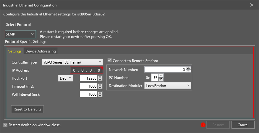
The available options are listed below.
| Property | Description |
| Controller Type |
Defines the type of Mitsubishi PLC/MC to communicate with: iQ-Q Series (3E Frame), or FX Series (1E Frame). The default value is iQ-Q Series 3E Frame. |
| IP Address | Defines the IP address of the Mitsubishi PLC/MC. Enter the IP address of the Mitsubishi PLC/MC to which the In-Sight vision system will connect. If an invalid address is entered, the Industrial Ethernet Configuration window indicates it with a red warning. |
| Host Port |
Defines the TCP port number, in decimal (Dec) or in hexadecimal (Hex) format, of the Mitsubishi PLC/MC. The allowed port number values are 0–196608 in Dec (or 0000–30000 in Hex). The default value is 12288 in Dec (or 0x3000 in Hex). Note:
|
| Timeout (ms) |
Defines the timeout (5 milliseconds to 30,000; default is 1,000 ms) for both read and write operations. Note: This parameter may potentially add time to the job; in the event that both the read and write operations were to fail, the amount of time added to the job would be twice the Timeout value, since both operations timeout would aggregate.
|
| Poll Interval (ms) |
Defines the time (5 milliseconds to 30,000; default is 1,000 ms) between successive polls of the Control block on the Mitsubishi PLC/MC . |
| Connect to Remote Station |
Enables the configuration of a master SLMP device that will be communicated with the In-Sight device. By default, the checkbox is unchecked and the In-Sight vision system is directly connected to the PLC/MC with an Ethernet Module specified by the entered IP address. When enabled, the following settings are available:
|