Inputs / Outputs
This application step is the place to configure the device I/O.
The Basic tab enables you to configure the behavior of the trigger and tune buttons, inputs, outputs and pulse encoder data. Height sensor data can also be set for devices for which it is relevant.
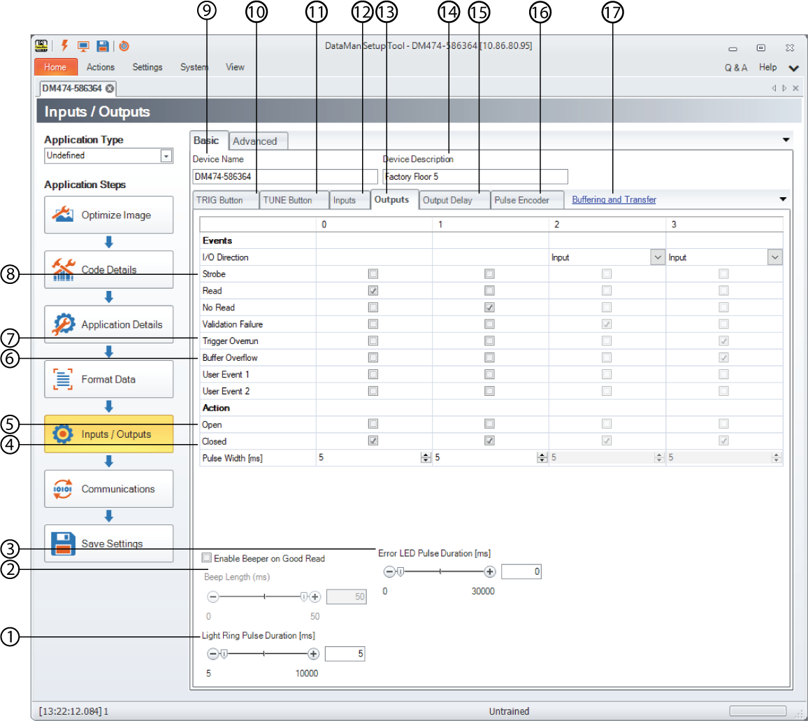
| 1 | Light Ring Pulse Duration | For readers with a light ring, the duration of the light ring’s illuminated state can be specified here in milliseconds. |
| 2 | Enable Beeper on Good Read | Set the Beep Length for good reads to a value between 0 and 50 ms. |
| 3 | Error LED Pulse Duration | You can move the slider to the desired millisecond that is used to determine how long the Error LED pulses on fixed-mount devices. The Error LED is found on the top of the device. Setting the slider to '0' causes the red error LED to turn off if the device log is retrieved, while every value above '0' causes the red error LED to turn off automatically after the selected time is expired. |
| 4 | Closed | The open or closed state means the state of the relay. If an Event happens from the list above, the output can be open or closed. For example, if a Read event happens, in the case of Closed, the output 0 will become output 1. Also, you can close an output line indefinitely by specifying a pulse width of 0 milliseconds, but be aware that any event that triggers this output line will cause it to remain closed until you cycle the power to the reader or clear outputs with a discrete input setting. |
| 5 | Open | |
| 6 | Buffer Overflow | Buffer Overflow means that it would be possible to acquire an image, but there is no space left to save it. In other words, images are acquired faster than they can be processed. One possible situation is when decoding takes longer than what the image/trigger interval is. |
| 7 | Trigger Overrun | Trigger Overrun means that the image could not be acquired because the camera was busy (for example, due to an ongoing burst or a long exposure). |
| 8 | Strobe | You can reserve an output for external illumination by checking Strobe on one of the output lines. You can also configure polarity by choosing Open or Closed in the appropriate Outputs column. |
| 9 | Device name | You can give the device a more meaningful name for your production environment, such as the location or the inspection task. |
| 10 | TRIG Button |
You can choose trigger button press functionality only in Single, Burst, and Self trigger modes. The 3 second button press action possibilities are the following:
You can also check Disable Reader Button if you do not want the physical TRIG button on the reader to work. When a checkbox is selected, the action assigned to an input does not occur immediately after activating the input. It takes place only when the next trigger is performed. |
| 11 | TUNE Button | Check the Disabled Reader Button if you do not want the physical TUNE button on the reader to work. |
| 12 | Inputs |
In addition to the different actions that you can use the input line for, here you can also set the change in signal that triggers an image acquisition (under Polarity). Use Debounce Delay to define how long the trigger signal must be detected to be recognized as valid. Use a shorter value to compensate for ESD line noise and higher values to compensate for noise in electromechanical relays. You might have to experiment with the setting to choose the most appropriate value for your production environment. |
| 13 | Outputs | The Outputs tab lets you configure the behavior of all output lines available to the reader. For any line you can configure the event and action of the output line. |
| 14 | Device Description | Device description is a freely editable text field where you can add notes to the device or important additional information. |
| 15 | Output Delay |
Set the output delay in Manual, Single, Burst, and Continuous trigger modes. When using a pulse encoder, you can specify the distance to the output and map the pulse to the distance. The distance to output value is corrected based on the value of the resolution (it is adjusted to the closest multiple of resolution rounded to millimeters). Use the Distance to output (mm) control to set the distance from trigger to when the result is output. |
| 16 | Pulse Encoder |
When using a pulse encoder, you can specify the distance to the output and map the pulse to the distance. The distance to output value is corrected based on the value of the resolution (it is adjusted to the closest multiple of resolution rounded to millimeters). Use the Resolution (mm) control to define the resolution. |
| 17 | Buffering and Transfer |
For more information on Buffering and Transfer, see Buffering and Transfer. |
The Advanced tab provides you with a table-style view of the settings you can configure on the Basic tab. In addition to setting the device name and description, you can configure the TRIG Button, the TUNE Button, Input and Output lines, Output Delay, and a Pulse Encoder.
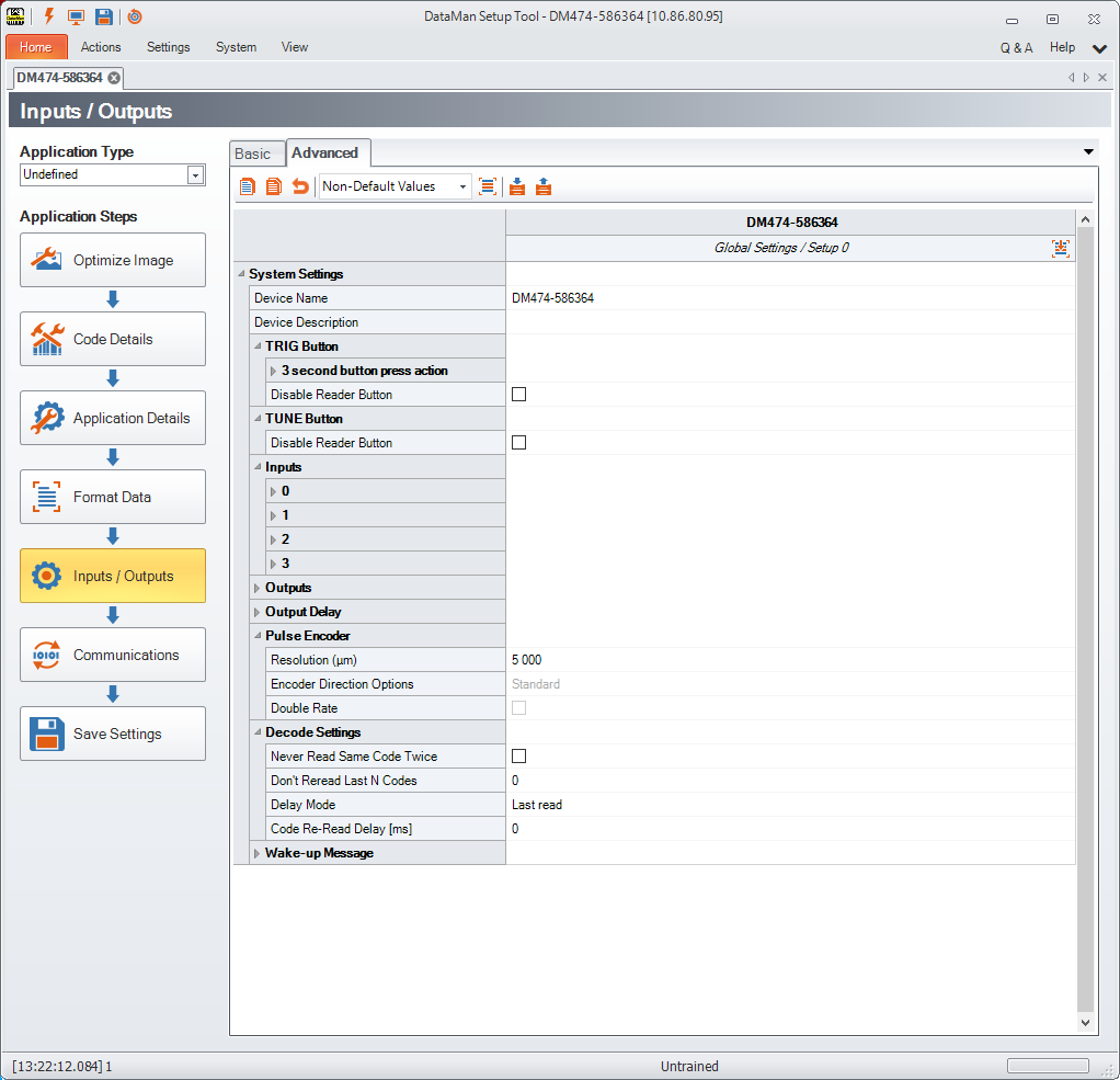
Under Decode Settings, you can set Never Read Same Code Twice. This suppresses the reporting of the same code string twice in a row and within a single trigger sequence when enabled. It is available for all trigger modes, but is only valid in Multicode Reading, since the only way to get more than one code in a single trigger sequence is in Multicode Readings. If Never Read the Same Code Twice is unchecked, the device re-reads and re-transmits the same code after the specified Code Re-Read Delay (in milliseconds).
Under Wake-up Message, enable or disable Output Diagnostic String on Wake-up. When enabled, the reader transmits a diagnostic string whenever the reader starts up. For Telnet connections the readers transmits the diagnostic string with each new connection. For serial connections, the baud rate is automatically set to 38,400 when the message is sent, regardless of the settings made in the Setup Tool.