Physical Layout of the Base Station
DMA-IBASE-01
|
|
|
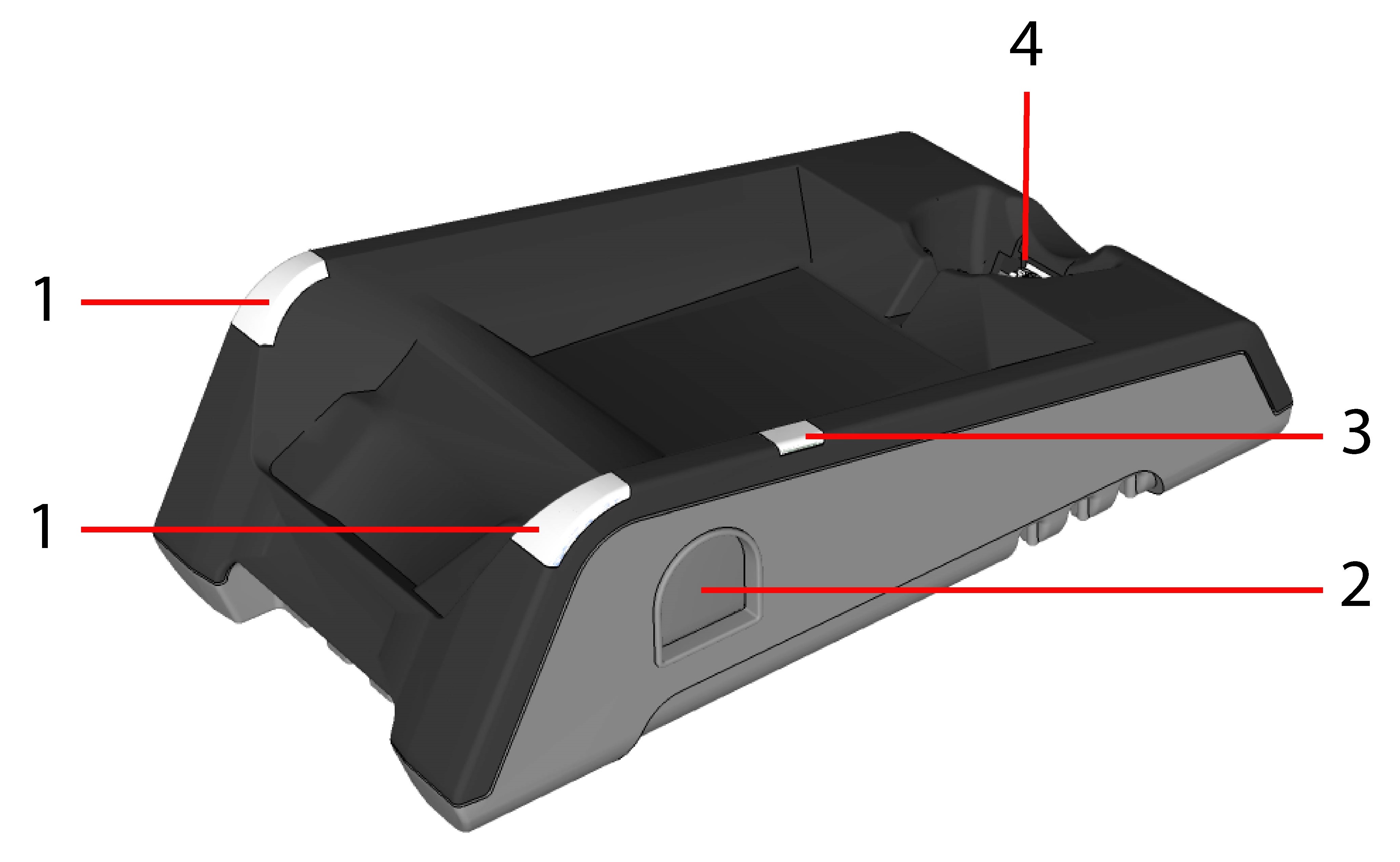
| 1 | Base station status indicators |
| 2 | Spare battery charger |
| 3 | Spare battery charger status indicator |
| 4 |
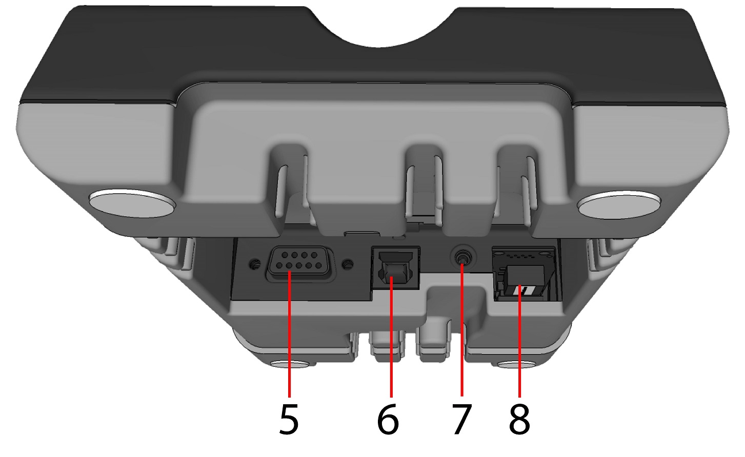
Connection point with the reader:
|
| 5 | RS-232 |
| 6 | USB |
| 7 | Power plug (24V, max. 13W) |
| 8 | Ethernet (with optional Class 3 PoE power) |
DMA-IBASE-BT-XX
|
|
|
| 1 | Base station status indicators |
| 2 |
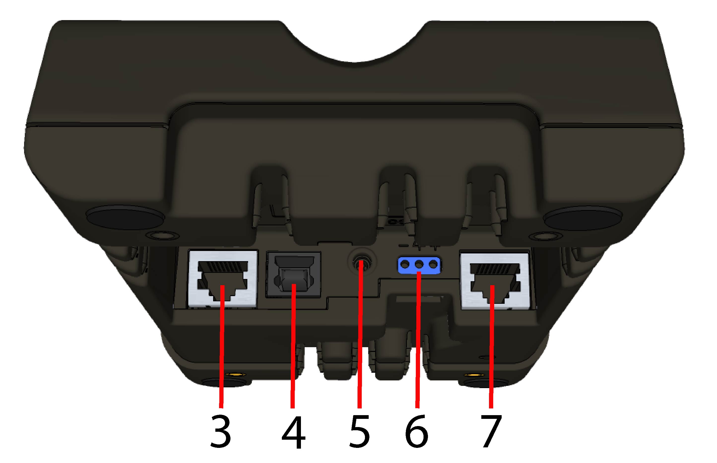
Connection point with the reader:
|
| 3 | RS-232 |
| 4 | USB |
| 5 | Power plug (24V, max. 15W) |
| 6 |
Alternative power supply connector (24V, max. 15W, polarity marked on the plastic part near the connector) Recommended wire diameter is 14-18 AWG |
| 7 | Ethernet |
Base station status indicators:
- Power: RED = base powered / BLINK = wrong reader in base
- Communication: BLUE = Wireless link / BLINK = Wireless communication
- Cradle connections: GREEN = reader properly inserted / BLINK = cradle USB interface communication
Note:
- DMA-IBASE-BT-01 does not support Ethernet
- DMA-IBASE-BT-02 supports Ethernet