Rockwell CompactLogix Examples
In the CompactLogix project, the Ethernet logic module is embedded in the CompactLogix processor module. It is displayed in the I/O Configuration tree as if it were a separate module on the backplane. This module is configured exactly like a ControlLogix Ethernet module.
The DataMan module is added in the same way for CompactLogix as for ControlLogix. Perform the following steps:
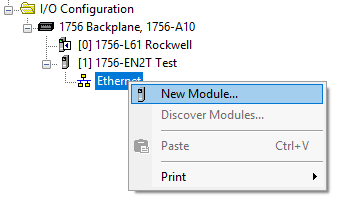
- Right-click the Ethernet node in the I/O Configuration tree and select New Module....
- From the Select Module dialog, choose your model of DataMan ID Reader from the list.

After the selection is completed, the configuration dialog for the DataMan ID Reader system is displayed. From this point on, configuration and programming are done exactly as shown in the ControlLogix section above.
Rockwell SLC 5/05 Example
This section outlines a PCCC (PC3) Communications configuration between a DataMan reader and the PLC. This example uses the Allen-Bradley SLC5/05 and Rockwell 500 software.
Setting up the PLC for Ethernet Communication
- From the RSLogix 500 software program, open the .RSS file, then open the Channel Configuration dialog (Project Folder > Controller Folder > Channel Configuration)
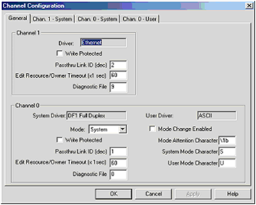
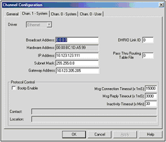
- The Allen-Bradley SLC has 2 channels available for configuration: Channel 1 (Ethernet); and Channel 0 (DF1 Full Duplex - serial). Click on the Chan. 1 - System tab.
- Configure Channel 1 (Ethernet) as necessary. Consult with a network administrator about settings.
-
Configure the Timeouts as required.
Message Instruction (MSG)
Message instructions can now be constructed within the application. Refer to the RSLogix 500 documentation for expanded instructions for developing messages.
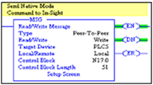
The following setup parameters can be configured within a Message (MSG) Instruction.
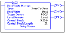
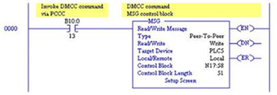
- Type: Peer-To-Peer. This cannot be modified.
- Read/Write: Select the function you want to perform on a DataMan reader. Read retrieves data from the DataMan; Write sends data to the DataMan.
- Target Device: Choose PLC5 to talk to a DataMan reader. This tells the SLC which communication protocol to use. The DataMan reader acts much like a ControlLogix controller (see Rockwell document 13862).
- Local/Remote: Choose Local to indicate that the DataMan reader is on the same network as the SLC; Remote tells the SLC that you will be communicating to a DataMan on another network. For remote communication, you have to direct the message through another device acting as a gateway to that secondary network. Typically, this could be an Allen-Bradley ControlLogix controller. (See the Rockwell documentation on how to address devices on other networks through a gateway.)
- Control Block: This is a temporary integer file that the MSG instruction uses to store data (that is, IP address, message type, and so on). This is typically not the user data to be sent.
- Control Block Length: This is automatically computed by the MSG instruction.
- Setup Screen: Selecting Setup Screen opens the Message Instruction Setup dialog.
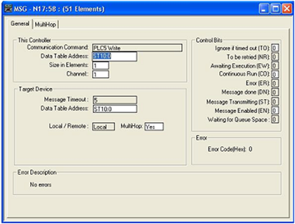
The following setup parameters can be configured within an MSG Instruction Setup screen.
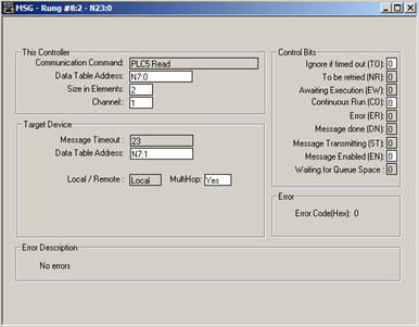
This Controller section:
- Communication Command: Make sure that it is the same command (READ/WRITE) as the command chosen on the first screen (as seen in MSG Instruction screen).
- Data Table Address: The location of the data file on the SLC where data will be written to (READ) or sent from (WRITE) (as seen in MSG Instruction screen). In this instance, 'N7:0', 'N' indicates the integer file, '7' indicates the file number 7, and '0' indicates the offset into that file (in this case, start at the 0th element).
- Size in Elements: The number of elements (or individual data) to read. In this example, two elements are being read.
- Channel: Depends on the configuration of the SLC. In the SLC, Channel 1 is the Ethernet port.
Target Device section:
- Message Timeout: Choose an appropriate length of time in which the DataMan reader can respond. If the DataMan does not respond within this length of time, the MSG instruction will error out. This parameter cannot be changed from this screen. The parameters entered in the Channel 1 setup dialog determine the Timeout Message.
- Data Table Address: The location on the DataMan reader where data will be read from or written to. In this instance, 'N7:1', 'N' indicates that the data is of type integer (16-bit); '7' is ignored by the DataMan (data is always being written to the Output Assembly, and read from the Input Assembly); and the '1' is the element offset from the start of the target buffer. For example: If the message were a READ, 'N7:2' would instruct to read the 3rd integer (the ':2' indicates the 3rd element, due to the SLC's 0-based index) from the Input Assembly (because a READ gets data from the DataMan's Input Assembly). If the message were a WRITE, 'N7:12' would indicate to write a (16-bit) integer value to the 13 integer location of the Output Assembly.
- Local/Remote: Set to Local or Remote, depending on the application.
- MultiHop: This setting depends on the information previously entered. For successful In-Sight communication, make sure that it is YES at this time.
Sending DMCC Commands from an SLC 5/0
- Configure the SLC5/05 as necessary.
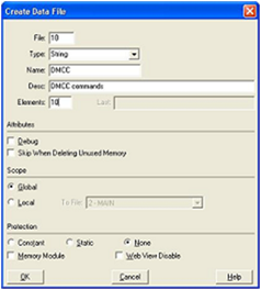
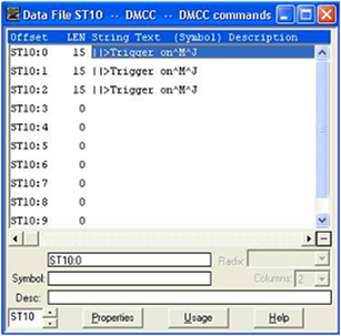
- Create a String Table that will hold your DMCC commands.
-
Add the required DMCC command strings to the Data File.
- Add a new Message (MSG) instruction to your ladder logic and configure it as shown in the following example:
- Enter the MSG Setup Screen and configure it as follows:
- Click the MultiHop tab and configure it as required (that is, set IP address of DataMan).
- When everything is configured, close the MSG window.
- Save your ladder logic, download it to the controller, then go online and set the controller in RUN mode.
- Trigger the message to send it to the DataMan reader.
| This Controller | Parameter | Description |
|---|---|---|
|
Data Table Address |
ST10:0 | First element from the String Table (ST) created above. |
| Size in Elements | 1 | Always set to 1. PCCC MSG only allows 1 string (therefore 1 command) to be sent at a time. |
| Channel | 1 | Set this to the Ethernet channel of your controller. |
| Target Device | Parameter | Description |
|---|---|---|
|
Message Timeout |
(From channel configuration dialog) | |
| Data Table Address | ST10:0 | This is the destination address. For DMCC commands, this will always be ST10:0. |
Message Instruction Results
The Enable (EN) bit of the message instruction will be set to 1 when the input to the instruction is set high. The Done (DN) bit will be set to 1 when DataMan has replied that the DMCC command was received and executed with success. If the Error bit (ER) is enabled (set to 1), it indicates a problem with the message instruction. If an error occurs, click the Setup Screen for the MSG instruction. The Error Code will be shown at the bottom of the window.
Using the Generic EtherNet/IP Profile
For devices without a specific Add-on Profile Rockwell provides a Generic EtherNet/IP profile. This profile allows you to create implicit messaging connections but lacks the automatic tag generation feature of a specific product Add-on Profile.
Establishing a Generic Implicit Messaging Connection
To set up an EtherNet/IP implicit messaging connection between a DataMan and a ControlLogix controller, add the DataMan reader to the ControlLogix I/O Configuration tree. This can be accomplished with the Rockwell provided generic profile.
To establish a generic implicit messaging connection with a ControlLogix PLC:
- Open RSLogix5000 and load your project (or select “File->New…” to create a new one).
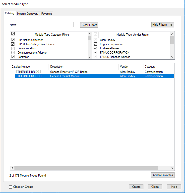
- From the I/O Configuration node, select the Ethernet node under the project Ethernet Module, right-click the icon and select New Module... from the menu:

-
From the Select Module Type dialog, choose the Allen-Bradley Generic Ethernet Module.
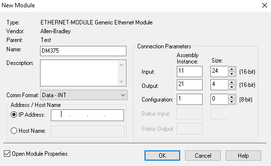
- After selecting it, the configuration dialog for the Generic Ethernet Module is displayed. Configure the following:
- Give the module a name.
- Enter your DataMan’s IP address.
- Set the Comm Format to “Data – INT”. This tells the module to treat the data as an array of 16-bit integers.
- Input Assembly: Set instance 11. Set the size to the amount of Input Assembly data you want the PLC to receive. Basic “Status” data requires 8 integers. The amount beyond that will be the actual decode result data. In the example below the size is set to 24 (8 for status + 16 for result data). This connection will receive the status info plus 32 bytes of result data.
- Output Assembly: Set instance 21. Set the size to 4 integers. This size is sufficient to send all required “Control” data to the DataMan.
- Configuration Assembly: Set instance 1. Set size to zero (not used).
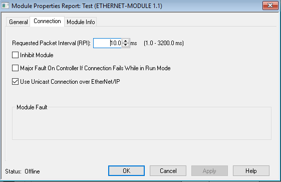
- Configure the connection rate. The rate at which data is transmitted/received is defined as the Requested Packet Interval (RPI). The RPI defines how frequently the data is transmitted/received over the connection. To optimize network performance, do not set this rate lower than absolutely required by a given application. You must not set it lower than half the median scan rate of the PLC ladder program. Setting it lower wastes bandwidth and does not improve processing performance.
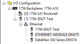
- After adding the generic module to ControlLogix, the I/O tree appears as follows.
- When the Generic Module is added to the I/O tree, RSLogix 5000 creates tags that map to the DataMan reader Input and Output Data (that is, the Input and Output Assembly Objects in the DataMan Reader). You can find these tags under the “Controller Tags” node of the project tree.
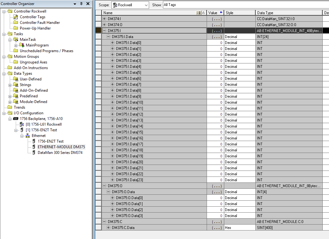
The tags are organized in three groups: Config “MyDM200:C”, Input “MyDM200:I”, and Output “MyDM200:O”. You can ignore the Config tags (not used). The Input tags represent all the data being received (from the DataMan). The Ouput tags represent all the data being sent (to the DataMan).
These tags are the data table representation of the DataMan Assembly Object contents. The PLC ladder is written to access these tag values. By monitoring or changing these tag values, the PLC ladder is actually monitoring and changing the DataMan Assembly Object contents.
Accessing Generic Implicit Messaging Connection Data
Unlike the DataMan Add-on Profile, the Generic Module profile does not automatically generate named tags representing the individual data items within an Assembly Object. Instead it simply generates an array of data according to the size of the connection you defined.
To access individual data items within an Assembly Object, manually select the correct tag offset and data subtype (if necessary) within the tag array that the Generic profile provided. This means that you have to manually reference the vendor documentation which defines the Assembly Objects.
Examples
Input Assembly “TriggerReady”: Bit 0 of word 0 of the Input Assembly. From the Input tag array for the DataMan select bit 0 of word 0.
Input Assembly “ResultLength”: Word 7 of the Input Assembly. From the Input tag array for the DataMan select word 7.

Output Assembly “Trigger”: Bit 1 of word 0 of the OutputAssembly. From the Output tag array for the DataMan select bit 1 of word 0.