Object Model
Modules
The PROFINET implementation on DataMan consists of seven I/O modules:
- Acquisition Control Module
- Acquisition Status Module
- Results Control Module
- Results Status Module
- SoftEvent Control Module
- User Data Module
- Result Data Module
Acquisition Control Module
Controls image acquisition. This module consists of data sent from the PLC to the DataMan device.
Slot number: 1
Total Module size: 1 byte
| Bit | Name | Description |
| 0 | Trigger Enable | Setting this bit enables triggering via PROFINET. Clearing this bit disables triggering. |
| 1 | Trigger |
Setting this bit triggers an acquisition when the following conditions are met:
|
| 2-7 | Reserved | Reserved for future use |
Acquisition Status Module
Indicates the current acquisition status. This module consists of data sent from the DataMan device to the PLC.
Slot number: 2
Total Module size: 3 bytes
| Bit | Name | Description |
| 0 | Trigger Ready | Indicates when the device is ready to accept a new trigger. Bit is True when “Trigger Enable” is set and the device is ready to accept a new trigger. |
| 1 | Trigger Ack | Indicates that the DataMan has received a new Trigger. This bit remains True as long as the “Trigger” bit remains True (that is, it is interlocked with the Trigger bit). |
| 2 | Reserved | Reserved for future use. |
| 3 | Missed Ack | Indicates that the DataMan was unable to successfully trigger an acquisition. Bit is cleared when the next successful acquisition occurs. |
| 4-7 | Reserved | Reserved for future use. |
| 8-23 | Trigger ID | ID value of the next trigger to be issued (16-bit integer). Used to match issued triggers with corresponding result data received later. This same value is returned in ResultID of the result data. |
Results Control Module
Controls the processing of result data. This module consists of data sent from the PLC to the DataMan device.
Slot number: 3
Total Module size: 1 byte
| Bit | Name | Description |
| 0 | Results Buffer Enable | Enables queuing of “Result Data”. If enabled, the current result data will remain until acknowledged (even if new results arrive). New results are queued. The next set of results are pulled from the queue (made available in the Result Data module) each time the current results are acknowledged. The DataMan will respond to the acknowledge by clearing the “Results Available” bit. Once the “Results Ack” bit is cleared the next set of read results will be posted and “Results Available” will be set True. If results buffering is not enabled newly received read results will simply overwrite the content of the Result Data module. |
| 1 | Results Ack | Bit is used to acknowledge that the PLC has successfully read the latest result data. When set True the “Result Available” bit will be cleared. If result buffering is enabled, the next set of result data will be pulled from the queue and “Result Available” will again be set True. |
| 2-7 | Reserved | Reserved for future use. |
Results Status Module
Indicates the acquisition and result status. This module consists of data sent from the DataMan device to the PLC.
Slot number: 4
Total Module size: 1 byte
| Bit | Name | Description |
| 0 | Decoding | Indicates that the DataMan is decoding an acquired image. |
| 1 | Decode Complete | Bit is toggled on the completion of a decode operation when the new results are made available (0 -> 1 or 1 -> 0). |
| 2 | Result Buffer Overrun | Indicates that the DataMan has discarded a set of read results because the results queue is full. Cleared when the next set of results are successfully queued. |
| 3 | Results Available | Indicates that a new set of read results are available, that is, the contents of the Result Data module are valid. Cleared when the results are acknowledged. |
| 4-6 | Reserved | Reserved for future use |
| 7 |
General Fault |
Indicates that a fault has occurred, that is, SoftEvent “Set Match String” or “Execute DMCC” error has occurred.
|
SoftEvent Control Module
Used to initiate a SoftEvent and receive acknowledgment of completion. Note that this is a bi-directional I/O module. Module data sent from the PLC initiates the SoftEvent. Module data sent by the DataMan device acknowledges completion.
Slot number: 5
Total Module size: 1 byte (input) and 1 byte (output)
Data written from the PLC to DataMan:
| Bit | Name | Description |
| 0 | Train Code | Bit transition from 0 -> 1 causes the train code operation to be invoked. |
| 1 | Train Match String | Bit transition from 0 -> 1 causes the train match string operation to be invoked. |
| 2 | Train Focus | Bit transition from 0 -> 1 causes the train focus operation to be invoked. |
| 3 | Train Brightness | Bit transition from 0 -> 1 causes the train brightness operation to be invoked. |
| 4 | Untrain | Bit transition from 0 -> 1 causes the untrain operation to be invoked. |
| 5 | Reserved | Reserved for future use |
| 6 | Execute DMCC | Bit transition from 0 -> 1 causes the DMCC operation to be invoked. Note that a valid DMCC command string must first be placed in “User Data” before invoking this event. |
| 7 | Set Match String | Bit transition from 0 -> 1 causes the set match string operation to be invoked. Note that match string data must first be placed in “User Data” before invoking this event. |
Data written from the DataMan to PLC:
| Bit | Name | Description |
| 0 | Train Code Ack | Indicates that the “Train Code” operation is complete |
| 1 | Train Match String Ack | Indicates that the “Train Match String” operation is complete |
| 2 | Train Focus Ack | Indicates that the “Train Focus” operation is complete |
| 3 | Train Brightness Ack | Indicates that the “Train Brightness” operation is complete |
| 4 | Untrain Ack | Indicates that the “Untrain” operation is complete |
| 5 | Reserved | Reserved for future use |
| 6 | Execute DMCC Ack | Indicates that the “Execute DMCC” operation is complete |
| 7 | Set Match String Ack | Indicates that the “Set Match String” operation is complete |
User Data Module
Data sent from a PLC to a DataMan to support acquisition, decode and other special operations. Currently this module is only used to support the “Execute DMCC” and “Set Match String” SoftEvents.
Slot number: 6
Total Module size:
4 + 16 (16 bytes of User Data)
4 + 32 (32 bytes of User Data)
4 + 64 (64 bytes of User Data)
4 + 128 (128 bytes of User Data)
4 + 250 (250 bytes of User Data)
| Byte | Name | Description |
| 0-1 | User Data Option |
Currently only used by “Set Match String” SoftEvent. Specifies which code target to assign the string (16-bit Integer). 0, assign string to all targets 1, assign string to 2D codes 2, assign string to QR codes 3, assign string to 1D / stacked / postal codes |
| 2-3 | User Data Length | Number of bytes of valid data actually contained in the “User Data” field (16-bit Integer). |
| 4... | User Data | Data sent from the PLC to the DataMan to support acquisition, decoding, and other special operations (array of bytes). |
Result Data Module
Read result data sent from a DataMan to a PLC.
Look into the Result Data Module for non-PROFINET related data if there is an acquisition problem on the reader. The "Result Code" part contains information about trigger overruns or buffer overflows that have occurred on the reader.
Slot number: 7
Total Module size:
8 + 16 (16 bytes of Result Data)
8 + 32 (32 bytes of Result Data)
8 + 64 (64 bytes of Result Data)
8 + 128 (128 bytes of Result Data)
8 + 246 (246 bytes of Result Data)
| Byte | Name | Description |
| 0-1 | Result ID | The value of the “Trigger ID” when the trigger that generated these results was issued. Used to match up triggers with corresponding result data (16-bit Integer). |
| 2-3 | Result Code |
Indicates the success or failure of the read that produced these results (16-bit Integer). Bit 0,1=read, 0=no read Bit 1,1=validated, 0=not validated (or validation not in use) Bit 2,1=verified, 0=not verified (or verification not in use) Bit 3,1=acquisition trigger overrun Bit 4,1=acquisition buffer overflow Bits 5-15 reserved |
| 4-5 | Result Extended | Currently unused (16-bit Integer). |
| 6-7 | Result Length | Actual number of bytes of read data contained in the “Result Data” field (16-bit Integer). |
| 8... | Result Data | Decoded read result data (array of bytes) |
Operation
SoftEvents
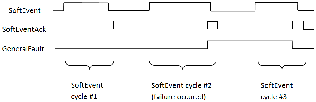
SoftEvents act as “virtual” inputs. When the value of a SoftEvent changes from 0 -> 1 the action associated with the event will be executed. When the action completes the corresponding SoftEventAck bit will change from 0 -> 1 to signal completion. The acknowledge bit will change back to 0 when the corresponding SoftEvent bit is set back to 0.
The “ExecuteDMCC” and “SetMatchString” SoftEvent actions require user supplied data. This data must be written to the UserData and UserDataLength area of the UserData Module prior to invoking the SoftEvent. Only one SoftEvent can be invoked at a time because both of these SoftEvents depend on the UserData.
General Fault Indicator
When a communication related fault occurs the “GeneralFault” bit will change from 0 -> 1. Currently the only fault conditions supported are SoftEvent operations. If a SoftEvent operation fails, the fault bit will be set. The fault bit will remain set until the next SoftEvent operation or until triggering is disabled and again re-enabled.
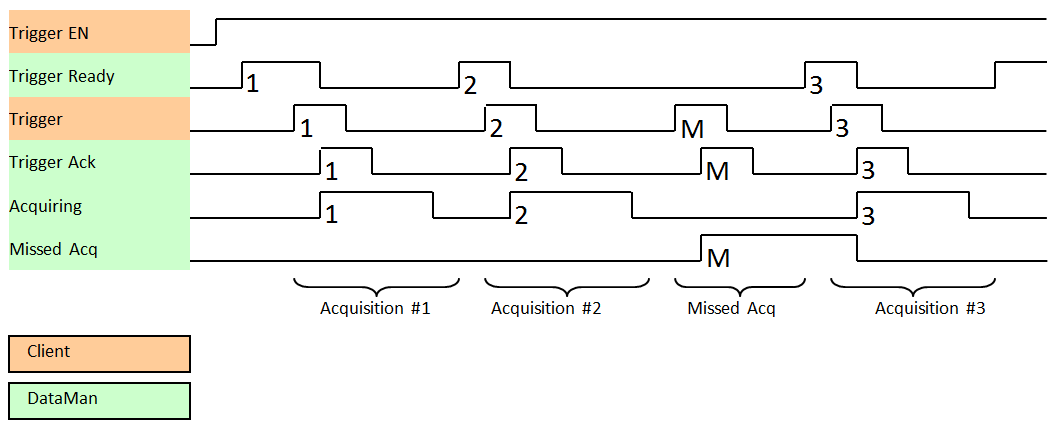
Acquisition Sequence
DataMan can be triggered to acquire images by several methods. It can be done explicitly by manipulating the Trigger bit of the Acquisition Control Module, it can be triggered by external hard wired input, and it can be triggered via DMCC. This section describes manipulating the Acquisition Control Module bits.
On startup the “Trigger Enable” bit will be False. It must be set to True to enable triggering. When the device is ready to accept triggers, the “Trigger Ready” bit will be set to True.
While the Trigger Ready bit is True, each time the reader detects the “Trigger” bit change from 0 to 1, it initiates an image acquisition. Make sure that the client (PLC) holds the bit in the new state until that same state value is seen back in the Trigger Ack bit. This is a necessary handshake to guarantee that the reader detects the change.
During an acquisition, the Trigger Ready bit will be cleared and the Acquiring bit will be set to True. When the acquisition is completed, the Acquiring bit will be cleared. The Trigger Ready bit is again set to True once the device is ready to begin a new image acquisition.
If results buffering is enabled, the device will allow overlapped acquisition and decoding operations. Trigger Ready will be set high after acquisition is complete but while decoding is still in process. This can be used to achieve faster overall trigger rates. If result buffering is not enabled, the Trigger Ready bit will remain low until both the acquisition and decode operations are complete.
To force a reset of the trigger mechanism, set the Trigger Enable bit to False, until the Trigger Ready bit is 0. Then, Trigger Enable can be set to True to re-enable acquisition.
As a special case, an acquisition can be cancelled by clearing the Trigger signal before the read operation is complete. This allows cancelling reads in Presentation and Manual mode if no code is in the field of view. To ensure that a read is not unintentionally cancelled, it is advised that the PLC hold the Trigger signal True until both TriggerAck and ResultsAvailable are True or DecodeComplete toggles state.
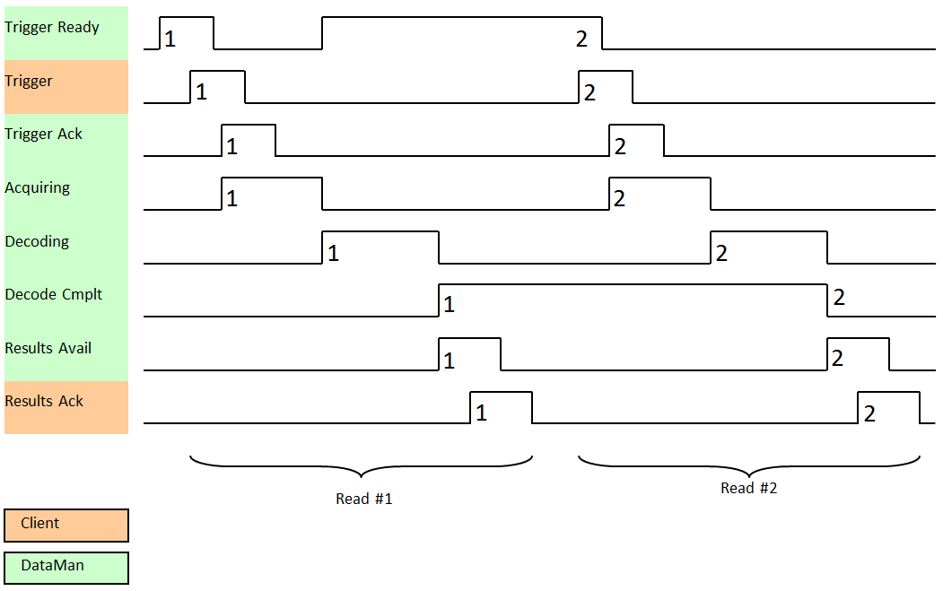
Decode / Result Sequence
After an image is acquired, it is decoded. While being decoded, the “Decoding” bit of the Result Status Module is set. When decode is complete, the Decoding bit is cleared and the “Decode Complete” bit is toggled.
The “Results Buffer Enable” bit determines how the reader handles decode results. If the Results Buffer Enable bit is set to False, then the decode results are immediately placed into the Results Module and Results Available is set to True.
If the Results Buffer Enable bit is set to True, the new results are queued. The earlier decode results remain in the Results Module until the client acknowledges them by setting the “Results Ack” bit to True. After the Results Available bit is cleared, make sure that the client sets the Results Ack bit back to False to allow the next queued results to be placed in to the Results Module. This is a necessary handshake to ensure the results are received by the DataMan client (PLC).
Behavior of DecodeStatusRegister
| Bit | Bit Name | Results if Buffering Disabled | Results if Buffering Enabled |
| 0 | Decoding | Set when decoding an image. | Set when decoding an image. |
| 1 | Decode Complete | Toggled on completion of an image decode. | Toggled on completion of an image decode. |
| 2 |
Results Buffer Overflow |
Remains set to zero. | Set when decode results could not be queued because the client failed to acknowledge a previous result. Cleared when the decode result is successfully queued. |
| 3 | Results Available | Set when new results are placed in the Results Module. Stays set until the results are acknowledged by setting Results Ack to true. | Set when new results are placed in the Results Module. Stays set until the results are acknowledged by setting Results Ack to true. |
Results Buffering
There is an option to enable a queue for decode results. If enabled, this allows a finite number of decode result data to queue up until the client (PLC) has time to read them. This is useful to smooth out data flow if the client (PLC) slows down for short periods of time or if there are surges of read activity.
If result buffering is enabled, the device will allow overlapped acquisition and decode operations. Depending on the application this can be used to achieve faster over all trigger rates. For more information, see the Acquisition Sequence description.
In general, if reads are occurring faster than results can be sent out, the primary difference between buffering or not buffering determines which results get discarded. If buffering is not enabled the most recent results are kept and the earlier result (which was not read by the PLC fast enough) is lost. The more recent result overwrites the earlier result. If buffering is enabled and the queue becomes full, the most recent results are discarded until space becomes available in the results queue.