Implicit Messaging
EtherNet/IP implicit messaging allows a DataMan reader’s inputs and outputs to be mapped into tags in the ControlLogix PLC. Once these connections are established, the data is transferred cyclically at a user defined interval (10ms, 50ms, 100ms, and so on).
The figure below represents Ethernet-based I/O through EtherNet/IP:
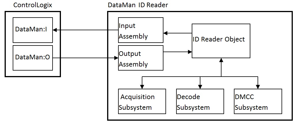
The Input Assembly and Output Assembly map various attributes (data) from the ID Reader object: The Input Assembly is the collection of DataMan reader data values sent to the PLC (PLC inputs); and the Output Assembly is the collection of data values received by the DataMan reader from the PLC (PLC outputs).
Establishing an Implicit Messaging Connection
To setup an EtherNet/IP implicit messaging connection between a DataMan and a ControlLogix controller, the DataMan reader must first be added to the ControlLogix I/O Configuration tree. The most efficient method is to use the Add-on Profile. This example assumes that the Add-on Profile has already been installed. If you do not have the Add-on Profile, see section Using the Generic EtherNet/IP Profile.
To establish an implicit messaging connection with a ControlLogix PLC:
- Open RSLogix5000 and load your project (or select “File -> New…” to create a new one).
From the I/O Configuration node, select the Ethernet node under the project Ethernet Module, right-click on the icon and select New Module... from the menu: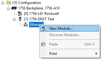
-
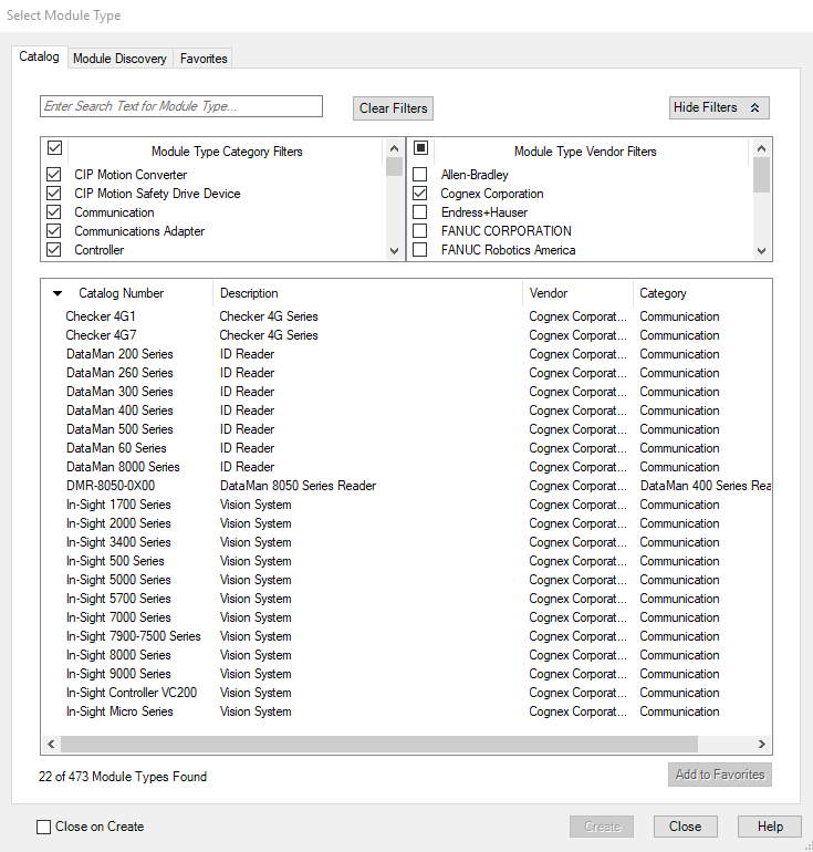
From the Select Module dialog, choose your model of DataMan ID Reader from the list.
-
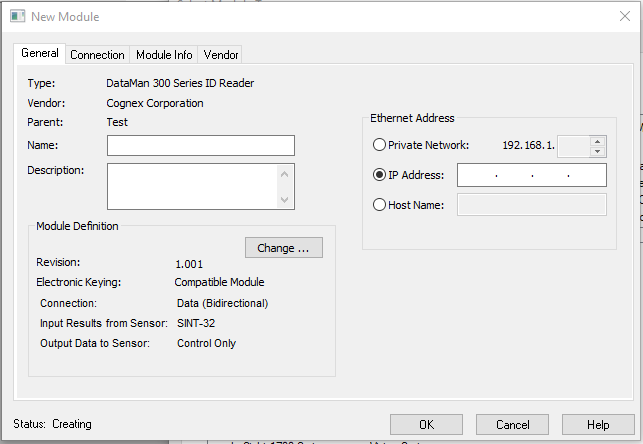
After selecting the device, the configuration dialog for the DataMan ID Reader system is displayed. Give the module a name and enter the DataMan’s IP address. The default is a bidirectional (send/receive) connection consisting of control, status, and 32 bytes of result data with keying disabled. To change this default connection, click the Change… button. If no change is required, skip the next step.
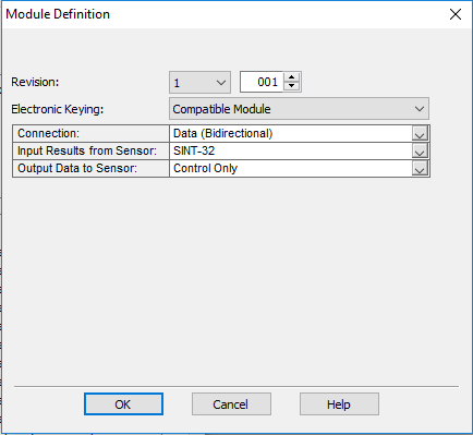
- Clicking the Change… button brings up the Module Definition dialog. This dialog is used to alter the connection configuration. You can change:
- DataMan revision
- Electronic keying
- Connection type (bidirectional/receive-only)
- Amount of data received (from the DataMan)
- Amount of data sent (to the DataMan)
- Vendor
- Product Type
- Catalog Number
- Major Revision
- Minor Revision
- The Module Types have to match
- Catalog Number has to match
- Major Revision has to match
- The Minor Revision of the module has to be equal to or greater than the one specified in the software.
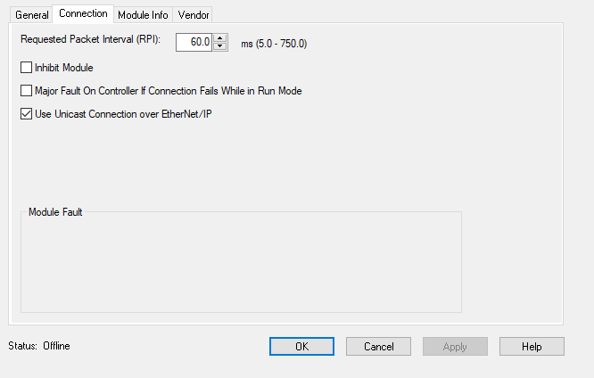
- The final step is configuring the connection rate. The rate at which data is transmitted/received is defined as the Requested Packet Interval (RPI). The RPI defines how frequently the data is transmitted/received over the connection. To optimize network performance, do not set this rate lower than required by a given application, or lower than half the expected maximum read rate of the user application. Setting it lower wastes bandwidth and does not improve processing performance.
-
Select the “Connection” tab of the “New Module” dialog to set the rate.
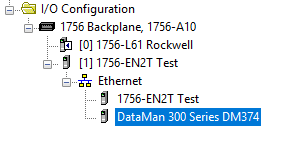
- After adding the module to ControlLogix, the I/O tree should appear as follows:
-
When the DataMan module is added to the I/O tree, RSLogix 5000 creates tags that map to the DataMan reader Input and Output Data (that is, the Input and Output Assembly Objects in the DataMan Reader). These tags can be found under the “Controller Tags” node of the project tree.
Note: The base name of these tags is the name you gave to the DataMan Module that you added to the I/O Configuration in the previous steps.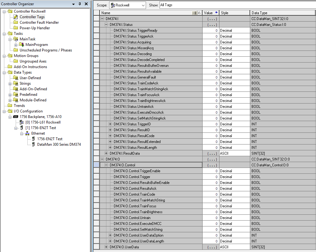
Electronic Keying: Defines the level of module type checking that is performed by the PLC before a connection is established.
Exact Match – All of the parameters must match or the connection will be rejected.
Compatible Module – To prevent the inserted module from rejecting the connection:
Disable Keying – The controller does not employ keying at all.
Connection: Defines the type of data flow.
Data (Bidirectional) – The connection sends data to the DataMan and receives data from the DataMan.
Input (Results only) – The connection only receives data from the DataMan. If more than one PLC needs to receive data from the same DataMan device, choose the Input connection option.
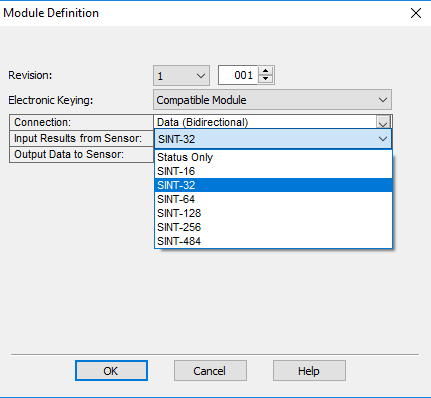
Input Results from Sensor: Defines the amount of data received on the connection from the DataMan. The minimum amount is the Status data only. The connection can be configured to also receive read result data. The amount of result data received is defined in fixed increments (16 bytes, 32 bytes, 64 bytes, and so on). Select the size to return no more than the largest code size to be read by the application. Setting the size larger wastes network bandwidth and diminishes performance.
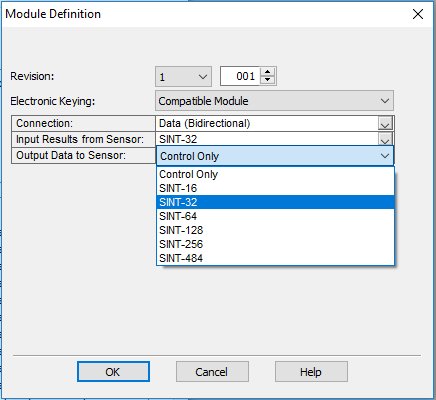
Output Data to Sensor: Defines the amount of data transmitted on the connection (to the DataMan). The minimum amount is the Control data only. The connection can be configured to also send user data. The amount of user data sent is defined in fixed increments (16 bytes, 32 bytes, 64 bytes, and so on). To enable User Data output, right-click the DataMan module and then go to Properties -> Change -> Output Data to Sensor.
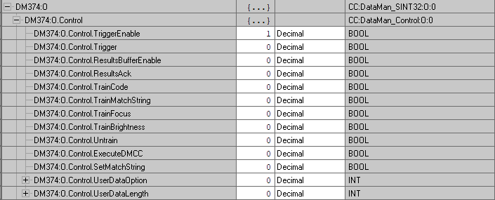
The tags are organized in two groups: Status and Control. The Status group represents all the data being received from the DataMan. The Control group represents all the data being sent to the DataMan.
These tags are the symbolic representation of the DataMan Assembly Object contents. The PLC ladder is written to access these tag values. By monitoring or changing these tag values the PLC ladder is monitoring and changing the DataMan Assembly Object contents.
Accessing Implicit Messaging Connection Data
One aspect of the Add-on Profile is that it automatically generates ControlLogix tags representing the connection data.
The generated tags are divided into two groups: Status and Control. The Status group represents all the data being received from the DataMan. The Control group represents all the data being sent to the DataMan.
Status tag group is the data the ControlLogix receives from the DataMan reader:
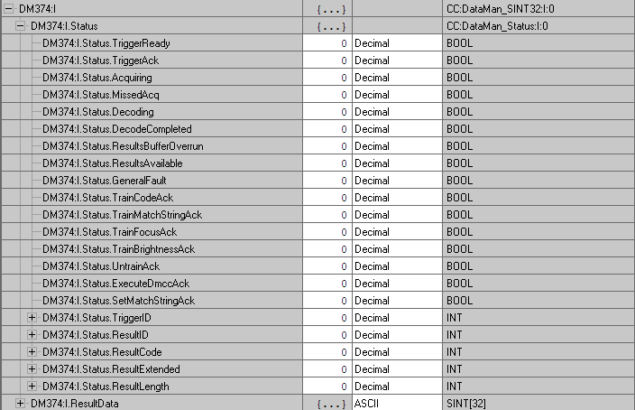
- TriggerReady: Indicates when the DataMan reader can accept a new trigger. This tag is True when the Control tag “TriggerEnable” has been set , and the sensor is not acquiring an image.
- TriggerAck: Indicates when the DataMan reader has been triggered (that is, the Control tag “Trigger” has been set to True). This tag stays set until the Trigger tag is cleared.
- Acquiring: Indicates when the DataMan reader is acquiring an image either by setting the Trigger bit or by an external trigger.
- MissedAcq: Indicates when the DataMan reader misses an acquisition trigger. It is cleared when the next successful acquisition occurs.
- Decoding: Indicates when the DataMan reader is decoding an acquired image.
- DecodeCompleted: Tag value is toggled (1 to 0 or 0 to 1) when a decode is completed.
- ResultsBufferOverrun: Indicates when the DataMan reader discards a set of decode results because the results queue is full. Cleared when the next set of results are successfully queued.
- ResultsAvailable: Indicates when a set of decode results are available (that is, the ResultID, ResultCode, ResultLength and ResultsData tags contain valid data).
- GeneralFault: Indicates when a fault has occurred (that is, SoftEvent “SetMatchString” or “ExecuteDMCC” error has occurred).
- TrainCodeAck: Indicates that the SoftEvent “TrainCode” is complete.
- TrainMatchStringAck: Indicates that the SoftEvent “TrainMatchString” has completed.
- TrainFocusAck: Indicates that the SoftEvent “TrainFocus” has completed.
- TrainBrightnessAck: Indicates that the SoftEvent “TrainBrightness” has completed.
- UnTrainAck: Indicates that the SoftEvent “UnTrain” has completed.
- ExecuteDmccAck: Indicates that the SoftEvent “ExecuteDMCC” has completed.
- SetMatchStringAck: Indicates that the SoftEvent “SetMatchString” has completed.
- TriggerID: Value of the next trigger to be issued. Used to match triggers issued with corresponding result data received later.
- ResultID: The value of TriggerID when the trigger that generated these results was issued. Used to match TriggerID’s with result data.
- ResultCode: Indicates success/failure of this set of results.
- Bit 0 ,1=read 0=no read
- Bit 1 ,1=validated 0=not validated (or validation not in use)
- Bit 2 ,1=verified 0=not verified (or verification not in use)
- Bit 3 ,1=acquisition trigger overrun
- Bit 4 ,1=acquisition buffer overflow (not the same as result buffer overflow).
- Bits 5-15 , reserved (future use)
- ResultExtended: Unused.
- ResultLength: Number of bytes of result data contained in the ResultData tag.
- ResultData: Decode result data. Control tag group is the data sent from the ControlLogix to the DataMan reader:
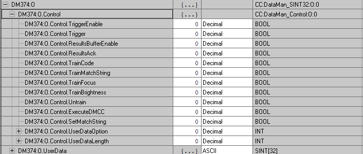
- TriggerEnable: Setting this tag enables EtherNet/IP triggering. Clearing this field disables the EtherNet/IP triggering.
- Trigger: Setting this tag triggers an acquisition if:
- The TriggerEnable tag is set.
- No acquisition/decode is currently in progress.
- The device is ready to trigger.
- ResultsBufferEnable: When set, the decode results are queued. Results are made available each time the PLC acknowledges the current results. The Decode ID, Decode Result and Decode ResultsData fields are held constant until the ResultsAck field acknowledged and set them. The DataMan reader responds to the acknowledgment by clearing the ResultsValid bit. Once the ResultsAck field is cleared, the next set of decode results are posted.
- ResultsAck: The ResultsAck tag is used to acknowledge that the PLC read the latest results. When ResultsAck is set, the ResultsAvailable tag will be cleared. If results buffering is enabled, the next set of results are made available when the ResultsAck tag is cleared again.
- TrainCode: Changing this tag from 0 to 1 invokes the train code operation.
- TrainMatchString: Changing this tag from 0 to 1 invokes the train match string operation.
- TrainFocus: Changing this tag from 0 to 1 invokes the train focus operation.
- TrainBrightness: Changing this tag from 0 to 1 invokes the train brightness operation.
- Untrain: Changing this tag from 0 to 1 invokes the un-train operation.
- ExecuteDMCC: Changing this tag from 0 to 1 invokes the DMCC operation. A valid DMCC command string must be written to UserData prior to invoking this SoftEvent.
- SetMatchString: Changing this tag from 0 to 1 invokes the set match string operation. The match string data must be written to UserData prior to invoking this SoftEvent.
- UserDataOption: Unused.
- UserDataLength: Number of bytes of user data contained in the UserData tag.
- UserData: This data is sent to the DataMan reader to support acquisition and/or decode.
Configure the DataMan module in RSLogix 5000 to manually add UserData to the output assembly.
Perform the following steps on a CompactLogix or ControlLogix PLC:
- Right click the DataMan module and select Properties.
- Under Module Definition, click Change.
- The Module Definition window pops up. Under the Output Data to Sensor drop-down menu, select SINT‑484.
- Click OK. RSLogix 500 is now updating the Module Definition.
The output assembly controller tags now list UserData as part of the output assembly.
Verifying Implicit Messaging Connection Operation
After the DataMan is added as an I/O device in a ControlLogix project and the project is downloaded to the controller, the I/O connection needs to be established. Once a successful connection is established, cyclic data transfers are initiated at the requested RPI.
To verify a proper I/O connection, follow these steps:
- Download the project to the ControlLogix controller.
- When the download completes, the project I/O indicator is I/O OK, indicating that the I/O connection is successfully completed.
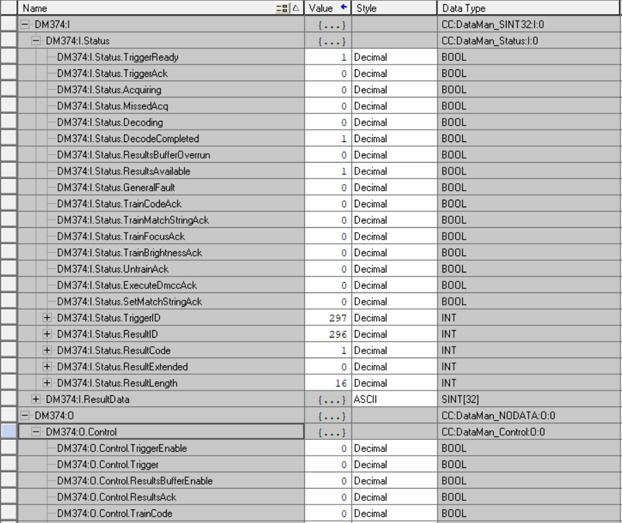
- The TriggerReady tag changes to 1. Triggering is now enabled.
- Whenever the Trigger tag is changed from 0 to 1, the DataMan reader acquires an image.
- After the acquisition/decode has completed, the DecodeCompleted tag will toggle, and the ResultsAvailable tag goes to 1. This example shows a successful read (ResultCode bit 0 = 1) and the read has returned 16 bytes of data (ResultLength=16). The data is in the ResultData tag.
To verify the correct, two-way transfer of I/O data, go to the controller tags in RSLogix and change the state of the TriggerEnable bit from 0 to 1: