DataMan 150 Cable Pinouts
The I/O module with USB has all signals on a SUB-D 15 connector with the following pinouts:
|
|
||
|---|---|---|
| PIN | Color | Signal |
| 1 | Brown | Reserved |
| 2 | Green | TxD (RS-232) |
| 3 | Green/Black | RxD (RS-232) |
| 4 | Red & Red/Black | GND |
| 5 | Brown/White | DC+ (system power, 5-24 VDC) |
| 6 | Blue | RTS |
| 7 | Blue/White | Output-0 |
| 8 | White | Input-0 |
| 9 | White/Black | Input-1 |
| 10 | Light Blue | CTS |
| 11 | Light Blue/Black | Output-1 |
| 12 | Light Blue/Yellow | Output-Common |
| 13 | Light Blue/Green | Input-Common |
| 14 | Yellow | Reserved |
| 15 | Yellow/Black | Reserved |
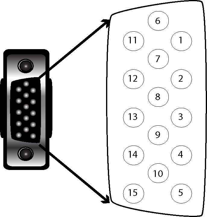
Note: Pin numbers are shown for cable connector, not I/O module.