EtherCAT Operation
SoftEvents
SoftEvents act as “virtual” inputs. When the value of a SoftEvent bit changes from 0 to 1, the action associated with the event is executed. When the action completes, the corresponding SoftEventAck bit will change from 0 to 1 to signal completion. The acknowledge bit will change back to 0 when the corresponding SoftEvent bit is set back to 0.
The ExecuteDMCC and SetMatchString SoftEvent actions require user-supplied data. This data must be written to the UserData Module prior to invoking the SoftEvent. Since both of these SoftEvents depend on the UserData, only one can be invoked at a time.
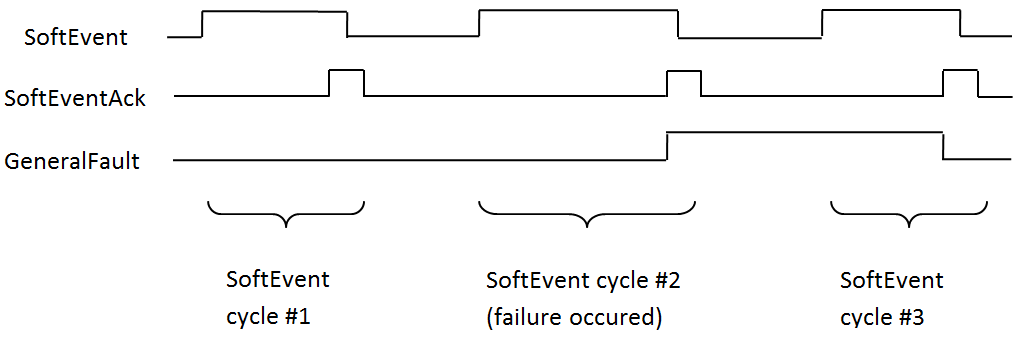
General Fault Indicator
When a communication-related fault occurs, the GeneralFault bit will change from 0 to 1. Currently the only fault conditions supported are SoftEvent operations. If a SoftEvent operation fails, the fault bit will be set. The fault bit will remain set until the next successful SoftEvent operation, or, until TriggerEnable is set to 0 and then back to 1.
Acquisition Sequence
You can trigger the reader to acquire images with the following methods:
-
By explicitly manipulating the Trigger bit of the Acquisition Control Module
-
Through external hardwired input
-
Through DMCC
This section describes manipulating the Control Object bits.
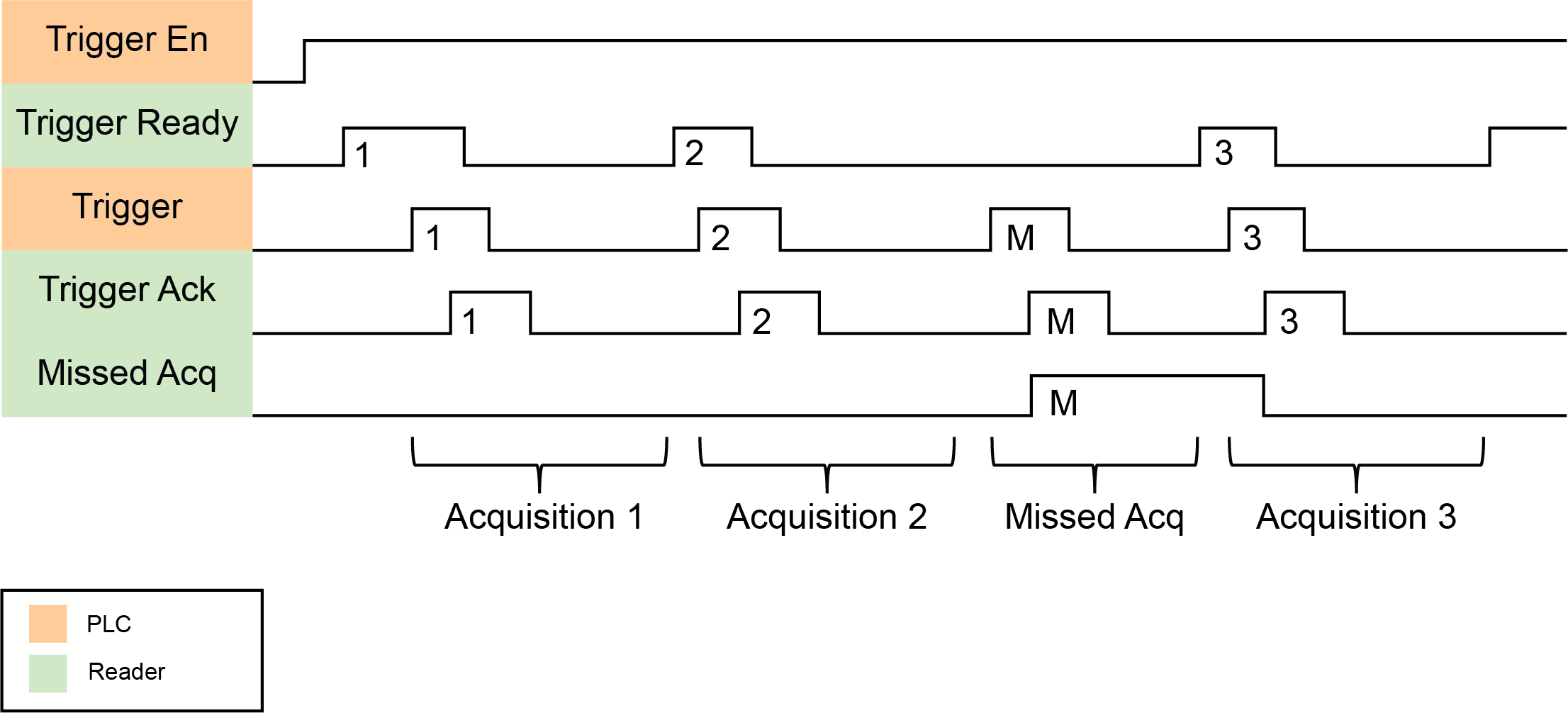
On startup, the TriggerEnable bit is False. It must be set to True to enable triggering. When the reader is ready to accept triggers, the reader sets the TriggerReady bit to True.
While the TriggerReady bit is True, each time the reader detects the Trigger bit change from 0 to 1, it initiates a read. Make sure that the PLC holds the bit in the new state until that same state value is seen in the TriggerAck bit. This is a necessary handshake to guarantee that the reader detects the change.
During an acquisition, the TriggerReady bit is cleared. When the reader is ready to begin another image acquisition, the TriggerReady bit is set to True again.
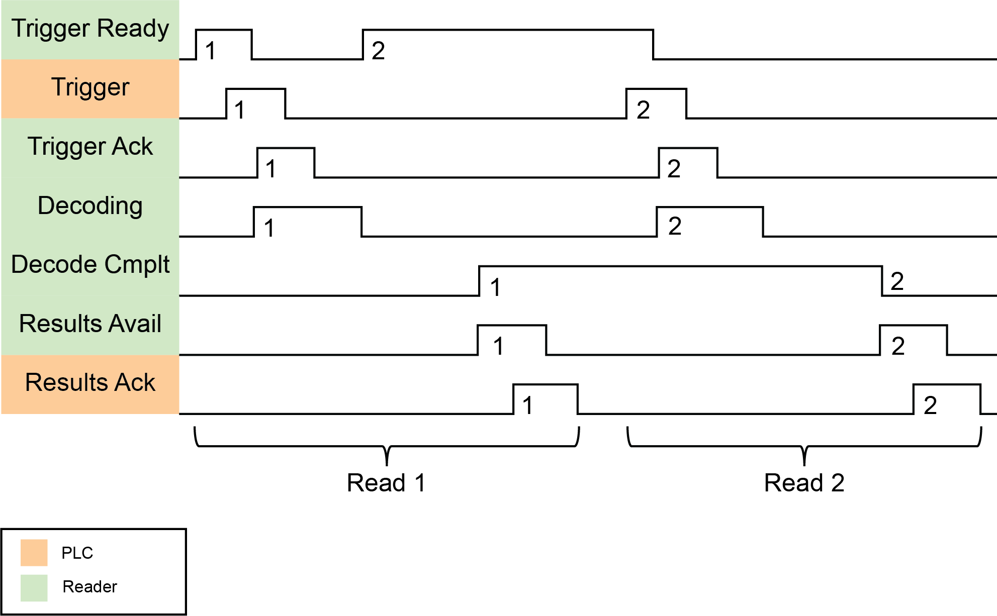
If results buffering is enabled, the reader allows overlapped acquisition and decoding operations. The TriggerReady bit is set high after the acquisition is complete but while the decoding is still in process. You can use this to achieve faster overall trigger rates. If result buffering is not enabled, the TriggerReady bit remains low until both the acquisition and decode operations are complete.
To force a reset of the trigger mechanism, set the TriggerEnable bit to False until the TriggerReady bit is also set to False. Then, the TriggerEnable bit can be set to True to reenable acquisition.
As a special case, you can cancel an acquisition by clearing the Trigger signal before the read operation is complete. This allows for canceling reads in Continuous and Manual mode if no code is in the field of view. To ensure that a read is not unintentionally canceled, make sure that the PLC holds the Trigger signal True until both the TriggerAck and ResultsAvailable bits are True (or the DecodeComplete bit toggles state).
Decode / Result Sequence
After an image is acquired, it is decoded. When the decoding is complete and a result is ready to be delivered, the reader toggles the DecodeComplete bit of the Status Object.
The Results Buffer Enable bit determines how the reader handles decode results. If BufferResultsEnable is set to False, then the decode results are immediately placed into DecodeResults, and the Results Available bit is set to True.
If the Results Buffer Enable bit is set to True, the new results are queued. The earlier decode results remain in the Results Object until the client acknowledges them by setting the Results Ack bit to True. After the Results Available bit is cleared, make sure that the client sets the Results Ack bit back to False to allow the next queued results to be placed in to the Results Module. This is a necessary handshake to ensure the results are received by the DataMan client (PLC).
Results Buffering
The Results Buffering feature allows a queue for decode results. When enabled, the feature queues a finite number of result data sets until the PLC (client) has time to read them. This smooths out data flow if the PLC slows down for short periods or if there are surges in read activity.
If the feature is enabled, the reader overlaps acquisition and decode operations. This can lead to faster over all trigger rates. When reads occur faster than results can be sent out (the queue is full), the most recent results are discarded until space becomes available in the results queue.
If the feature is disabled, the more recent results overwrite the earlier results. The most recent results are kept. Earlier results are discarded if the PLC does not read them fast enough.
If the queue overflows while the feature is disabled:
-
The difference between the TriggerID and ResultID values becomes greater than 1. This difference represents the number of reads that occurred but could not be queued because the queue was full.
-
The number of lost reads equals TriggerID - ResultID - 1.
-
After the next read, the ResultID value returns to the typical operating value of TriggerID - 1.
Long Codes Behavior with Results Buffering for EtherCAT
During non-buffered operation, only the selected result data array that is available in the Inspection Result object can store read results. If you need to read codes longer than the selected result data array, enable Results Buffering and perform the steps below. Before doing so, make sure the ResultsAvailable bit in the Status object is 1 and Result length contains a longer length than bytes available in the array.
You can choose from the following frame sizes in bytes:
-
32
-
64
-
96
-
128
-
224
-
256
-
480
The process is the following:
-
Read out the selected result data array.
-
Set ResultsAck bit in the Control object to 1 to acknowledge reading.
-
ResultsAvailable bit in the Status object goes to 0.
-
-
Lower ResultsAck bit in the control object to 0 again.
-
ResultValid bit in the status object goes back to 1.
-
ResultID in the Inspection Result Header stays the same because no new result is available.
-
ResultID in the Inspection Result Header stays the same because no new result is available.
-
Result length now contains the length of the remaining data of the full code: last length of the result data array.
-
-
Read out the remaining data.
-
If not finished, continue with step 2. Don’t forget to also acknowledge the last readout, so that the next Result can be delivered.
Result Fragmentation
The Result Fragmentation feature splits decode result strings into fragments if the strings are too large for the Results Data field. The fragments are then pushed to the buffer like normal results. Then, the PLC reads the fragments one by one.
Result Fragmentation depends on Result Buffering. This means that results are only fragmented if Result Buffering is enabled.
Operation of Result Fragmentation
The PLC does not automatically reassemble the result string. Once the PLC reads a result fragment, you have to copy the fragment to a new user-defined variable. After this, you have to set and clear the ResultAck bit, which updates the Decode Results with the next fragment. This process continues until all fragments have been sent to the PLC.
In contrast, if Results Buffering is disabled, large decode result strings are cut off to fit into the Results Data field, which means that the end of the string gets lost.
Identifying Decode Result Chunks
Decode result fragments look like normal results. To identify result fragments, look at the Result ID:
-
The Result ID of the result fragments are the same.
-
The Result ID of the last result fragment is different from the Result ID of the next result.
The Result Length of the result fragments represents the amount of data left to be sent.
-
The Result Length of the result fragment is lower or equal to the Result Buffer Size.
-
When the Result Length equals 0, there are no more fragments left for that decode result.
Maximum Result Data Length
Without results fragmentation, result data is truncated to fit into the results data buffer size. Depending on the protocol, the result buffer size can be fixed or configurable.
The Result Fragmentation feature allows processing of up to 50 times longer results, depending on the results buffering queue size, with an absolute limit of 65535 characters.
The maximum number of result characters sent in a single EtherCAT frame is 478 bytes.
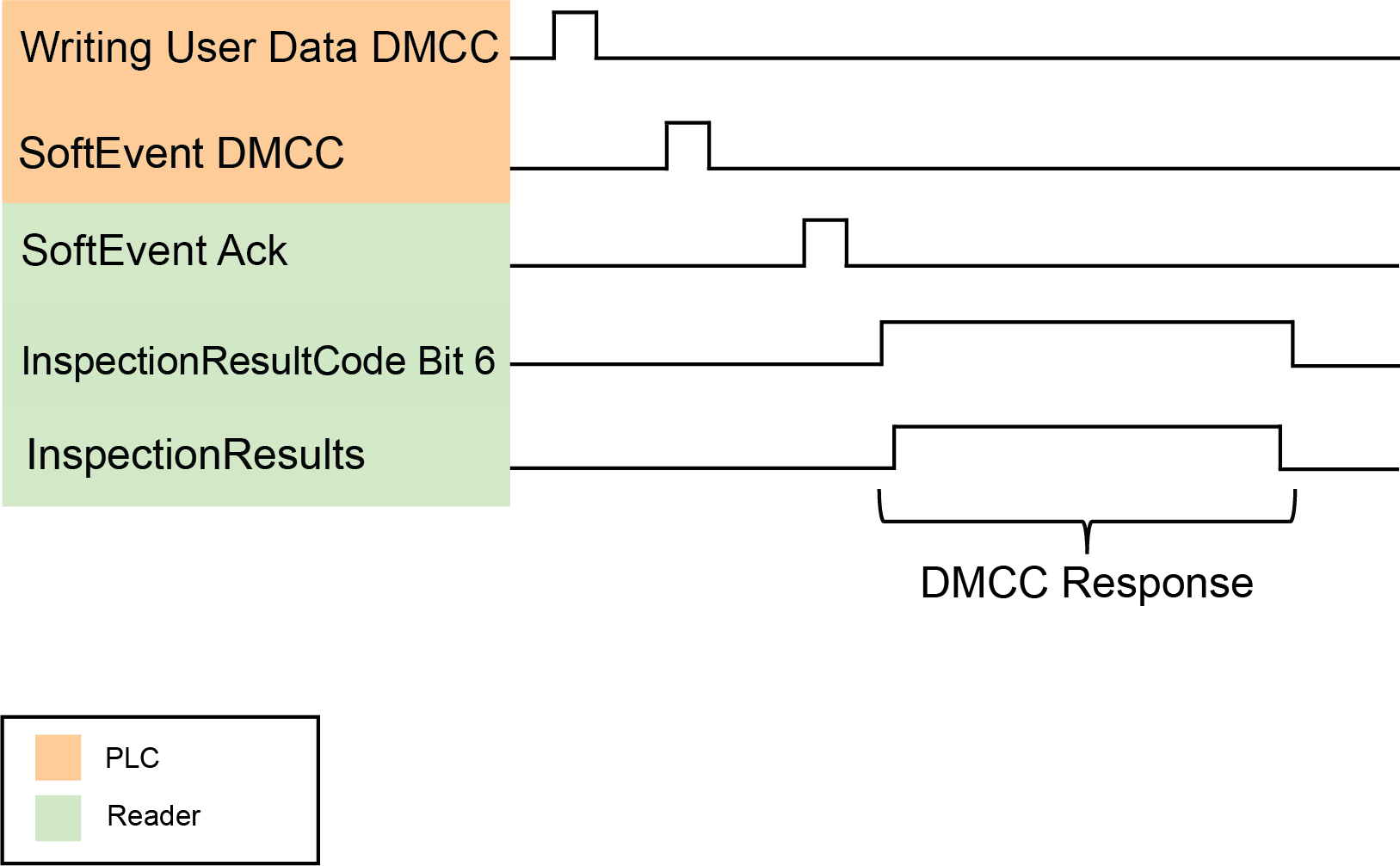
DMCC Result Feedback from PLC
The DMCC Result Feedback feature allows the reader to send DMCC responses back to the PLC.
By default, this feature is off. If enabled, the reader sends DMCC responses to the PLC using the same mechanism as for read results. To distinguish DMCC results from read results, bit 6 is flagged in the ResultCode field.
To enable the feature, use the FFP.DMCC-RESULTS command. Changing this configuration does not require you to reboot or reconnect reader.
You can use DMCC Result Feedback in combination with Results Fragmentation.