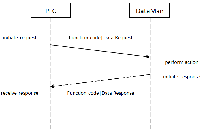
Modbus TCP Operation
Modbus TCP is a request/response based protocol. All communications are originated from the PLC. The reader acts as server.
Requests
To initiate actions or control data transfer, the PLC changes the state of certain bits of the Control block and sends requests to the reader.
After each request, the reader will process changes in state of the bits in the Control block. Some state changes require additional communications with the PLC, such as writing updated acknowledge bit values or reading a new string command. These additional communications are handled automatically by the reader. Other state changes initiate activities such as triggering a read or executing a SoftEvent. The reader performs the requested action and later reports the results.
Typical Sequence Diagram
Handshaking
A number of actions are accomplished by means of a logical handshake between the reader and the PLC (triggering, transferring results, executing SoftEvents, string commands, and so on). This is done to ensure that both sides of a transaction know the state of the operation on the opposite side. Network transmission delays will always introduce a finite time delay in transfer data and signals. Without this handshaking, it is possible that one side of a transaction might not detect a signal state change on the other side. Any operation that has both an initiating signal and corresponding acknowledge signal will use this basic handshake procedure.
The procedure involves a four-way handshake.
- Assert signal
- Signal acknowledge
- De-assert signal
- De-assert acknowledge
The requesting device asserts the signal to request an action (set bit 0 -> 1). When the target device detects the signal and the requested operation has completed, it asserts the corresponding acknowledge (set bit 0 -> 1). When the requesting device detects the acknowledge, it de-asserts the original signal (1 -> 0). Finally, when the target device detects the original signal de-asserted, it de-asserts its acknowledge (bit 0 -> 1). To function correctly both sides must see the complete assert/de-assert cycle (0 -> 1 and 1 -> 0). The requesting device should not initiate a subsequent request until the cycle completes.
Acquisition Sequence
DataMan can be triggered to acquire images by several methods. It can be done by setting the Trigger bit or issuing a trigger String Command. It can also be done via DMCC command (Telnet) or hardwired trigger signal. The Trigger bit method will be discussed here.
On startup, TriggerEnable will be False. It must be set to True to enable triggering via the Trigger bit. When the device is ready to accept triggers, the reader will set the TriggerReady bit to True.
While the TriggerReady bit is True, each time the reader detects the Trigger bit change from 0 -> 1, it will initiate a read. The Trigger bit should be held in the new state until that same state value is seen in the TriggerAck bit (this is a necessary handshake to guarantee that the trigger is seen by the reader).
During an acquisition, the TriggerReady bit will be cleared and the Acquiring and Decoding bits will be set to True. When the acquisition is completed, the Acquiring and Decoding bits will be cleared. When the device is ready to begin another image acquisition, the TriggerReady bit will again be set to True.
The reader allows acquisitions to overlap with the decoding of previous acquisitions. The Trigger Ready bit is set high after the acquisition is complete, while decoding may still be in progress. The Decoding bit is deprecated and only mirrors the behavior of the Acquiring bit. If trigger queuing is active or other trigger sources can interfere, the Trigger Ready bit may not be reliable. As result, conflicting trigger overruns may occur, which are reported in Bit 3 of the Result Code word of the Output Data Block.
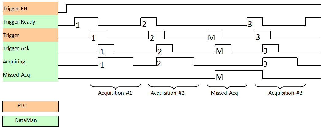
To force a reset of the trigger mechanism set the TriggerEnable to False until TriggerReady is also set to False. Then, TriggerEnable can be set to True to re-enable acquisition.
As a special case, an acquisition can be cancelled by clearing the Trigger signal before the read operation has completed. This allows for the cancellation of reads in Presentation and Manual mode if no code is in the field of view. To ensure that a read is not unintentionally cancelled, it is advised that the PLC hold the Trigger signal True until both TriggerAck and ResultsAvailable are True (or DecodeComplete toggles state).
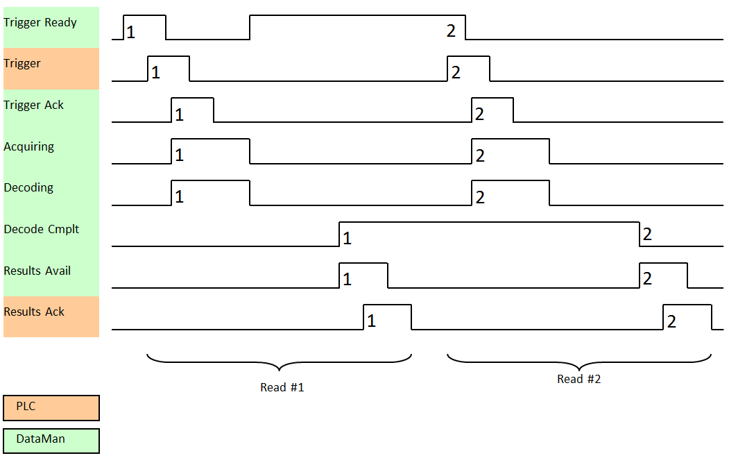
Decode / Result Sequence
After an image is acquired, it is decoded. When the decoding is complete and a result is ready to be delivered, the reader toggles the DecodeComplete bit of the DecodeStatusRegister.
Decode results are reported asynchronously to the Output Data block. If BufferResultsEnable is set to False, then the decode results are immediately placed into DecodeResults, and the Results Available bit is set to True.
If ResultsBufferEnable is set to True, the new results are queued in a buffer and DecodeComplete is toggled. The earlier read results remain in the Output Data block until they are acknowledged by the PLC. After the acknowledgment handshake, if there are more results in the queue, the next set of results will be placed in the Output Data block and ResultsAvailable is set to True.
Results Buffering
The Results Buffering feature allows a queue for decode results. When enabled, the feature queues a finite number of result data sets until the PLC (client) has time to read them. This smooths out data flow if the PLC slows down for short periods or if there are surges in read activity.
If the feature is enabled, the reader overlaps acquisition and decode operations. This can lead to faster over all trigger rates. When reads occur faster than results can be sent out (the queue is full), the most recent results are discarded until space becomes available in the results queue.
If the feature is disabled, the more recent results overwrite the earlier results. The most recent results are kept. Earlier results are discarded if the PLC does not read them fast enough.
If the queue overflows while the feature is disabled:
-
The difference between the TriggerID and ResultID values becomes greater than 1. This difference represents the number of reads that occurred but could not be queued because the queue was full.
-
The number of lost reads equals TriggerID - ResultID - 1.
-
After the next read, the ResultID value returns to the typical operating value of TriggerID - 1.
Result Fragmentation
The Result Fragmentation feature splits decode result strings into fragments if the strings are too large for the Results Data field. The fragments are then pushed to the buffer like normal results. Then, the PLC reads the fragments one by one.
Result Fragmentation depends on Result Buffering. This means that results are only fragmented if Result Buffering is enabled.
Enabling Result Fragmentation
To enable or disable Result Fragmentation, you have the following options:
-
Use the FFP.RESULT-FRAG DMCC.
-
Use SoftEvent 6 to enable the Results Buffering and Result Fragmentation features from the PLC.
Operation of Result Fragmentation
The PLC does not automatically reassemble the result string. Once the PLC reads a result fragment, you have to copy the fragment to a new user-defined variable. After this, you have to set and clear the ResultAck bit, which updates the Decode Results with the next fragment. This process continues until all fragments have been sent to the PLC.
In contrast, if Results Buffering is disabled, large decode result strings are cut off to fit into the Results Data field, which means that the end of the string gets lost.
Identifying Decode Result Chunks
Decode result fragments look like normal results. To identify result fragments, look at the Result ID:
-
The Result ID of the result fragments are the same.
-
The Result ID of the last result fragment is different from the Result ID of the next result.
The Result Length of the result fragments represents the amount of data left to be sent.
-
The Result Length of the result fragment is lower or equal to the Result Buffer Size.
-
When the Result Length equals 0, there are no more fragments left for that decode result.
Maximum Result Data Length
Without results fragmentation, result data is truncated to fit into the results data buffer size. Depending on the protocol, the result buffer size can be fixed or configurable.
The Result Fragmentation feature allows processing of up to 50 times longer results, depending on the results buffering queue size, with an absolute limit of 65535 characters.
The maximum number of result characters for ModbusTCP is up to 4000 bytes (configurable).
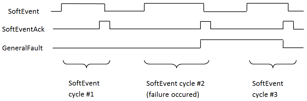
SoftEvents
SoftEvents act as virtual inputs. When the value of a SoftEvent bit changes from 0 to 1, the action associated with the event is executed. When the action completes, the corresponding SoftEventAck bit changes from 0 to 1 to signal completion.
The SoftEvent and SoftEventAck form a logical handshake. After SoftEventAck changes to 1, make sure that the original SoftEvent is set back to 0. When that occurs, SoftEventAck is automatically set back to 0.
The “ExecuteDMCC” and “SetMatchString” SoftEvent actions require user supplied data. Make sure that this data is written to the UserData and UserDataLength area of the Input Data block prior to invoking the SoftEvent. Only one SoftEvent can be invoked at a time, because both of these SoftEvents depend on the UserData.
String Commands
The String Command feature allows you to execute string-based DMCCs over the SLMP or the Modbus TCP protocol connection. The DMCC is sent to the reader through the String Command block. The DMCC result is returned through the String Command Result block. Initiating a command and notification of completion is accomplished by signaling bits in the Control and Status blocks.
To execute a DMCC, the command string is placed in the data field of the String Command block. The command string consists of standard ASCII text. The same command format is used for a serial (RS-232) or Telnet connection. The string does not need to be terminated with a null character. Instead, the length of the string (that is, the number of ASCII characters) is placed in the length field of the String Command block.
After executing the DMCC, the result string is returned in the String Command Result block. Similar to the original command, the result string consists of ASCII characters in the same format that is returned through a serial or Telnet connection. Also, there is no terminating null character. Instead the length of the result is returned in the Command String Result length field. The Command String Result block also contains a numeric result code. This allows you to determine the success or failure of the command without having to parse the text string. The values of the result code are defined in the DMCC documentation.
DMCC Result Feedback from PLC
The DMCC Result Feedback feature allows the reader to send DMCC responses back to the PLC.
By default, this feature is off. If enabled, the reader sends DMCC responses to the PLC using the same mechanism as for read results. To distinguish DMCC results from read results, bit 6 is flagged in the ResultCode field.
To enable the feature, use the FFP.DMCC-RESULTS command. Changing this configuration does not require you to reboot or reconnect reader.
You can use DMCC Result Feedback in combination with Results Fragmentation.
General Fault Indicator
When a communication-related fault occurs, the “GeneralFault” bit changes from 0 to 1. The only fault conditions supported are SoftEvent operations. If a SoftEvent operation fails, the fault bit will be set. The fault bit will remain set until the next successful SoftEvent operation, or until TriggerEnable is set to 0 and then back to 1.