DM280 EtherCAT Layout
The image and table below show the elements of the reader.
|
|
|
|---|---|
| Number | Description |
| 1 | Power I/O Breakout cable connector |
| 2 | USB-C slot (with plastic cover) |
| 3 | Network connector (EtherCAT) |
| 4 | Ethernet connector |
| 5 | Illumination LEDs |
|
6 |
LED aimers |
| 7 | EtherCAT Link Activity Out LED1 |
| 8 | Trigger button |
| 9 | EtherCAT Status LED1 |
| 10 | Tune button |
| 11 | EtherCAT Link Activity In LED1 |
| 12 | Indicator LEDs |
| 13 | Power LED indicator |
| 14 | Train status/Trigger status LED indicator |
| 15 | Good/bad read LED indicator |
| 16 | Communication LED indicator |
| 17 | Error LED indicator |
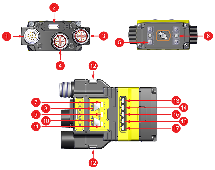
1For more information on the EtherCAT LEDs, see EtherCAT Indicators.