Operation
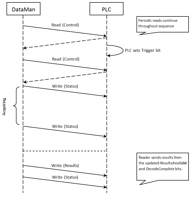
SLMP Protocol is a command/response based protocol. All communications are originated from the DataMan reader. The reader must send read requests to the PLC at a periodic interval to detect changes in the control bits.
Scanning
To initiate actions or control data transfer, the PLC changes the state of certain bits of the Control block. Since only the reader can initiate communications, the reader scans (that is, reads the Control block from the PLC) at a periodic rate. This rate is user-defined.
After each scan, the reader will process changes in state of the bits in the Control block. Some state changes require additional communications with the PLC, such as writing updated acknowledge bit values or reading a new string command. The reader handles these additional communications automatically. Other state changes initiate activities such as triggering a read or executing a SoftEvent. The reader performs the requested action and later reports the results.
For any transfer (read or write), the entire interface block is sent, even if only one field within the block has changed value. The protocol implementation will minimize network usage by grouping as many value changes as logically possible into a single transfer.
Typical Sequence Diagram
Handshaking
A number of actions are accomplished by means of a logical handshake between the reader and the PLC: triggering, transferring results, executing SoftEvents, string commands, and so on. This ensures that both sides of a transaction know the state of the operation on the opposite side. Network transmission delays always introduce a finite time delay in transfer data and signals. Without this handshaking, one side of a transaction might not detect a signal state change on the other side. Any operation that has both an initiating signal and corresponding acknowledge signal uses this basic handshake procedure.
The procedure involves a four-way handshake.
- Assert signal
- Signal acknowledge
- De-assert signal
- De-assert acknowledge
The requesting device asserts the signal to request an action (set bit 0 to 1). When the target device detects the signal and the requested operation is complete, it asserts the corresponding acknowledge (set bit 0 to 1). When the requesting device detects the acknowledge, it de-asserts the original signal (1 to 0). Finally, when the target device detects the original signal de-asserted, it de-asserts its acknowledge (bit 0 to 1). To function correctly, both sides must see the complete assert/de-assert cycle (0 to 1 and 1 to 0). The requesting device should not initiate a subsequent request until the cycle completes.
Acquisition Sequence
DataMan can be triggered to acquire images by several methods. It can be done via the SLMP Protocol by setting the Trigger bit or issuing a trigger String Command, by DMCC (Telnet), or hardwired trigger signal. This section describes the Trigger bit method.
On startup the TriggerEnable will be False. It must be set to True to enable triggering via the SLMP Protocol Trigger bit. When the device is ready to accept triggers, the reader will set the TriggerReady bit to True.
While the TriggerReady bit is True, each time the reader detects the Trigger bit change from 0 to 1, it initiates a read. Make sure that the Trigger bit is held in the new state until that same state value is seen in the TriggerAck bit. This is a necessary handshake to guarantee that the reader detects the trigger.
During an acquisition, the TriggerReady bit will be cleared and the Acquiring bit will be set to True. When the acquisition is completed, the Acquiring bit will be cleared. When the device is ready to begin another image acquisition, the TriggerReady bit will again be set to True.
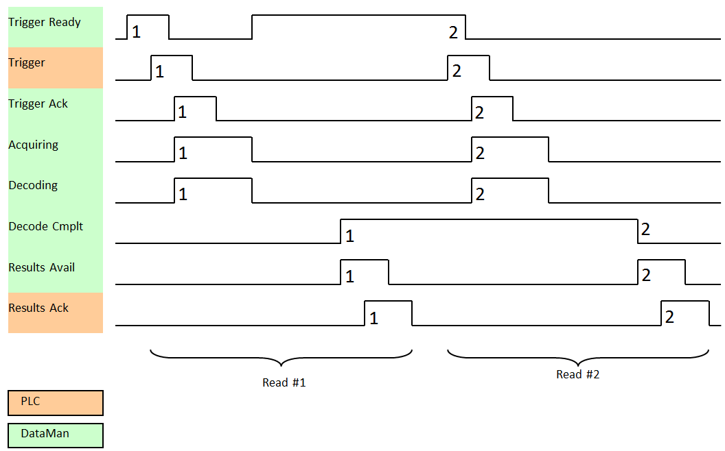
The reader allows acquisitions to overlap with the decoding of previous acquisitions. The Trigger Ready bit is set high after the acquisition is complete, while decoding may still be in progress. The Decoding bit is deprecated and only mirrors the behavior of the Acquiring bit. If trigger queuing is active or other trigger sources can interfere, the Trigger Ready bit may not be reliable. As result, conflicting trigger overruns may occur, which are reported in Bit 3 of the Result Code word of the Output Data Block.
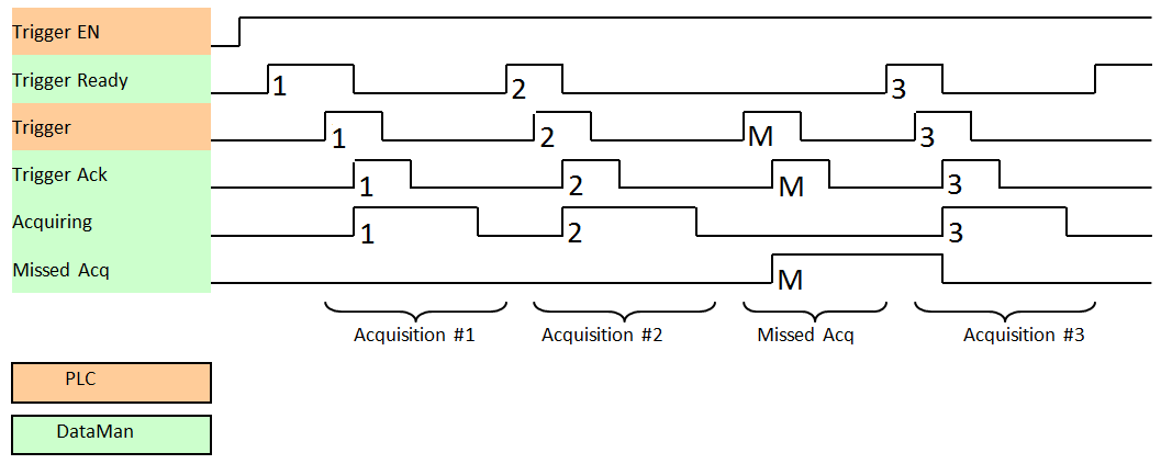
To force a reset of the trigger mechanism, set the TriggerEnable to False until TriggerReady is also set to False. Then, TriggerEnable can be set to True to re-enable acquisition.
As a special case, an acquisition can be cancelled by clearing the Trigger signal before the read operation is complete. This allows for canceling reads in Presentation and Manual mode if no code is in the field of view. To ensure that a read is not unintentionally cancelled, make sure that the PLC holds the Trigger signal True until both TriggerAck and ResultsAvailable are True (or DecodeComplete toggles state).
Decode / Result Sequence
After an image is acquired, it is decoded. When the decoding is complete and a result is ready to be delivered, the reader toggles the DecodeComplete bit of the DecodeStatusRegister.
Decode results are reported asynchronously to the Output Data block. If BufferResultsEnable is set to False, then the decode results are immediately placed into DecodeResults, and the Results Available bit is set to True.
If ResultsBufferEnable is set to True, the new results are queued in a buffer and DecodeComplete is toggled. The earlier read results remain in the Output Data block until the PLC acknowledges them. After the acknowledgment handshake, if there are more results in the queue, the next set of results will be placed in the Output Data block and ResultsAvailable is set to True.
Results Buffering
There is an option to enable a queue for read results. If enabled, this allows a finite number of sets of result data to be queued up until the PLC has time to read them. This is useful to smooth out data flow if the PLC slows down for short periods of time.
In general, if reads are occurring faster than results can be sent out, the primary difference between buffering or not buffering determines which results get discarded. If buffering is not enabled, the most recent results are kept and the earlier result, which the PLC did not read quickly enough, is lost. The more recent result overwrites the earlier result. If buffering is enabled and the queue becomes full, the most recent results are discarded until space becomes available in the results queue.
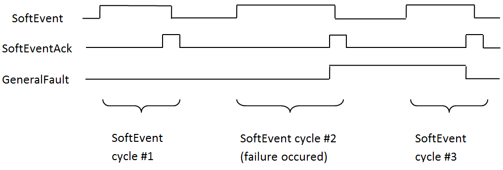
SoftEvents
SoftEvents act as “virtual” inputs. When the value of a SoftEvent bit changes from 0 to 1, the action associated with the event is executed. When the action completes, the corresponding SoftEventAck bit will change from 0 to 1 to signal completion.
The SoftEvent and SoftEventAck form a logical handshake. After SoftEventAck changes to 1, the original SoftEvent should be set back to 0. When that occurs, SoftEventAck will automatically be set back to 0.
String Commands
The DataMan SLMP Protocol implementation includes a String Command feature. This feature allows you to execute string-based DMCCs over the SLMP protocol connection. The DMCC is sent to the reader through the String Command block. The DMCC result is returned through the String Command Result block. Initiating a command and notification of completion is accomplished by signaling bits in the Control and Status blocks.
To execute a DMCC, the command string is placed in the data field of the String Command block. The command string consists of standard ASCII text. The same command format is used for a serial (RS-232) or Telnet connection. The string does not need to be terminated with a null character. Instead, the length of the string (that is, the number of ASCII characters) is placed in the length field of the String Command block.
After executing the DMCC, the result string is returned in the String Command Result block. Similar to the original command, the result string consists of ASCII characters in the same format that is returned through a serial or Telnet connection. Also, there is no terminating null character. Instead the length of the result is returned in the Command String Result length field. The Command String Result block also contains a numeric result code. This allows you to determine the success or failure of the command without having to parse the text string. The values of the result code are defined in the DMCC documentation.
General Fault Indicator
When an SLMP Protocol communication-related fault occurs, the “GeneralFault” bit will change from 0 to 1. Currently the only fault conditions supported are SoftEvent operations. If a SoftEvent operation fails, the fault bit will be set. The fault bit will remain set until the next successful SoftEvent operation, or, until TriggerEnable is set to 0 and then back to 1.