Define a Region for Inspection with CogImageConvertTool
Now that you have configured a simulated camera as the device from which to obtain your images, let's refine the inspection scope with VisionPro's CogImageConvertTool. However, before doing this, take time to become familiar with the landscape in which your task blocks exist: the Task window.
The Task Window
When you create a Single Camera project, a Task window opens in the Sequence Editor area of Cognex Designer, prepopulated various project elements as shown below.
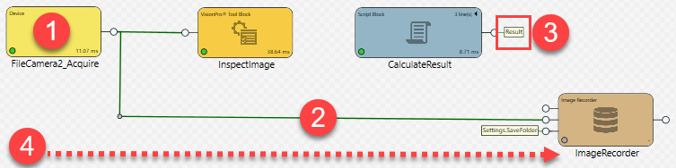
These components are the following:
- Task blocks that depict processing within a common single-camera vision application. The Task window graphically describes how your vision application processes images and data. From acquiring the image (hereafter called "acquisition") through processing and output, each block represents a task that performs a discrete function.
- When using a project template as a basis (such as the Single Camera project used in this tutorial), connector lines are drawn by default between the Acquire and InspectImage and ImageRecorder blocks. These connectors pass links to data between task blocks.
- You can also assign Tags to those links. Tags enable your data to be referenced in Cognex Designer applications.
- The task blocks execute left-to-right across the grid of the Task window, which acts as a graphical time-line. For example, in the window below, the task block Acquire executes before the task block InspectImage because, in left-to-right sequence, the Acquire block has been placed first.
Configure InspectImage Tool Block
Let's start by configuring the VisionPro tool block InspectImage, which runs CogImageConvertTool. We'll use CogImageConvertTool to isolate a specific part of the Jell-O box image for further processing by CogBlobTool, configured later in this tutorial.
Define the image area that you want to inspect by configuring the InspectImage tool block as described below:
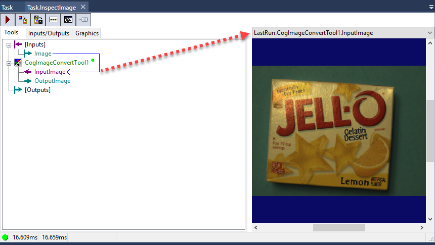
- In the Task window, double-click the InspectImage tool block. An instance of VisionPro Quick Build opens in the Sequence Editor. The tab associated with this instance is labeled Task.InspectImage.
- Verify that an image has been acquired. in the right-pane preview area of the Task.InspectImage window, as shown below. If it has not been acquired, select the Task window and Run All tasks.
-
Now, let's isolate a particular region of the Jell-O box. To do so, first click the Task.InspectImage window, and then double-click CogImageConversionTool1.
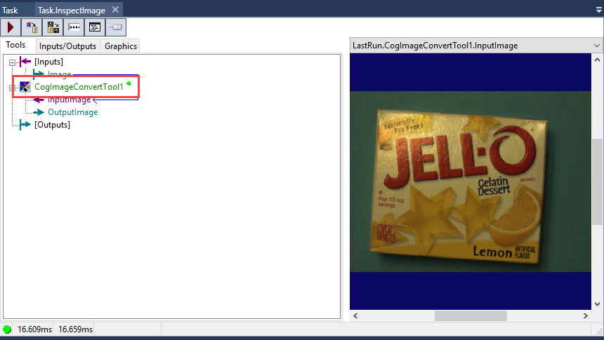
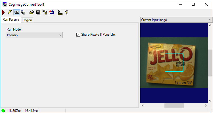
This opens the CogImageConvertTool1 window.
-
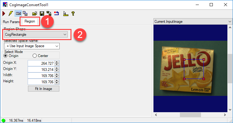
Select the Region tab of the window (1). Then, select CogRectangle from the Region Shape drop down box (2).
-
Select and re-size the blue CogRectangle in the image until it overlays the entire right-side of the frame containing the Jell-O box. You may have to increase the size of the CogImageConvertTool1 dialog box to do this.
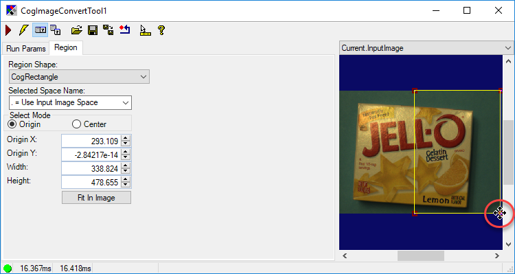
- Once you re-sized the CogRectangle, close theCogImageConvertTool1 dialog box.
- Run Task.InspectImage by clicking the
 (Run) button.
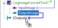
 - In the Task.InspectImage window, draw a connector between CogImageConvertTool1's OutputImage element and the [Outputs] element to indicate that this partial image is the output that you want the InspectImage block to produce as output. Do this as follows:
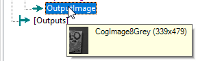
Select CogImageConvertTool1 > OutputImage. Notice the black-and-white preview image, CogImage8Grey, that is displayed.
Click and then and drag the CogImageConvertTool1's OutputImage element to the [Outputs] element.
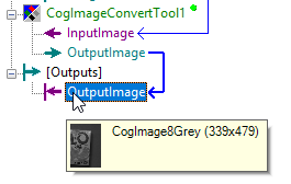
Under [Outputs], a new element named OutputImage is then created. Verify that OutputImage contains the right-side of the Jell-O box by pointing your mouse at the OutputImage label. Again, a black-and-white preview (CogImage8Grey) of the partial image should display, as in the previous step.
- Click the Task tab to switch back to the Task window, and click
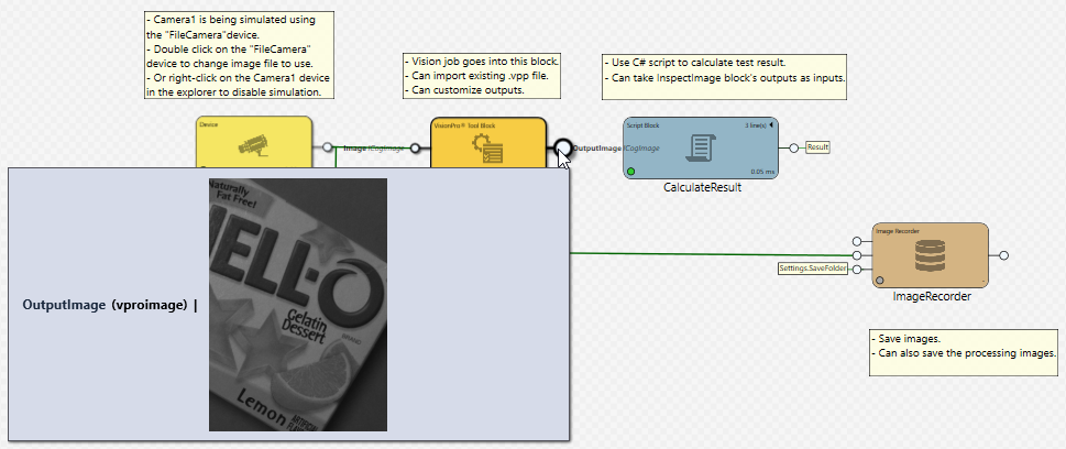
 to re-run the task sequence, since you modified CogImageConvertTool. Notice that a new output pin has appeared on the InspectImage task block. Point your mouse at this pin, and notice that both the link to the data (OutputImage) and the value's tag (vproimage) are displayed along with the cropped image preview you defined earlier in Step 5.
 - Close the Task.InspectImage window.
- Before moving on the next step in this tutorial, save your project by clicking File > Save All.
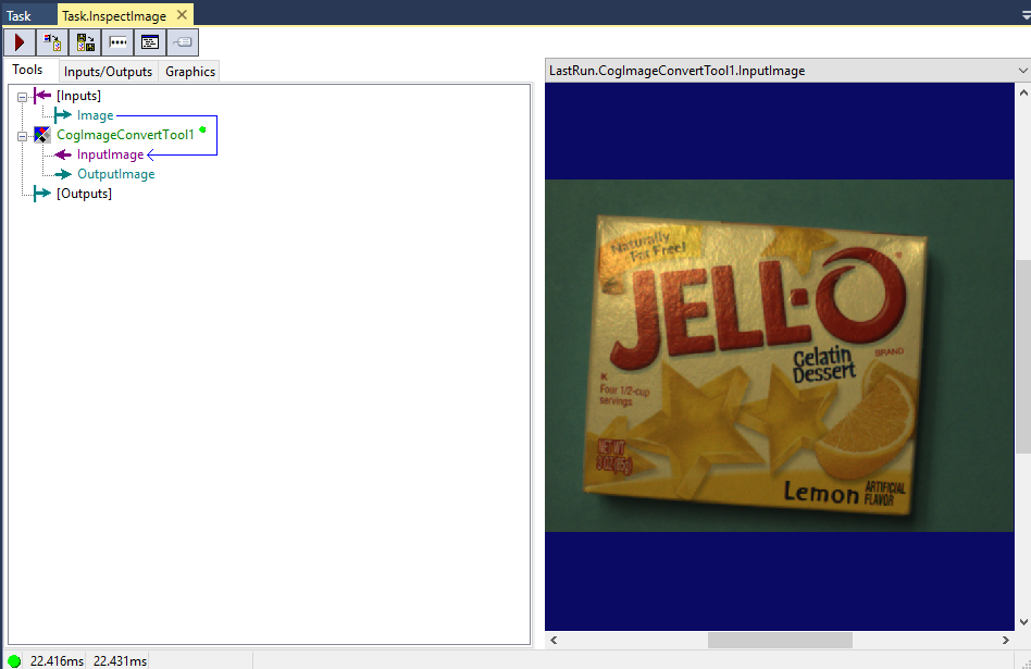
Note that in the Task.InspectImage window, the [Inputs] > Image and CogImageConvertTool1 > InputImage entries are connected with an arrow. This connection mirrors the connection between the Acquire block and the InspectImage block in the Task window of Cognex Designer. As such, the image displayed in the VisionPro QuickBuild tool as LastRun.CogImageConvertTool1.InputImage is the same image acquired by the Acquire block in the task.
With this procedure, you successfully cropped the image you acquired during the Select an Image Source and Acquire Your Image procedure by modifying it with the VisionPro tool CogImageConvertTool.
In the next step (Process Image for Defects with CogBlobTool), we'll process this cropped image for defects (blobs) by using another VisionPro tool, CogBlobTool.