Network Data Model
The Cognex Network Data Model (NDM) allows both the vision application (written by you in Cognex Designer) and the corresponding PLC application (running on the PLC) to interact with a familiar, platform-appropriate interface.
On the PLC, the NDM is represented as a signal table. The signal table defines a collection of status and control signals that the PLC and the vision application use to communicate. Signals are represented as named sections consisting of one or more bits of memory on the PLC. The overall signal table is represented as a pair of sub-tables that define the overall layout of the signal bits:
- A status table, that contains the signals and memory that are set by the vision application and read by the PLC application.
- A control table, that contains the signals and memory that are set by the PLC application and read by the vision application.
The PLC implementation also includes blocks of memory that can be used for sending configuration information to the vision application (such as the name of a job to load ) and for sending results data to the PLC (such as a decoded string or a collection of part measurements).
Within the vision application, the NDM is represented as a collection of notification functions and events. Your application invokes the notification functions to raise or lower the state of a signal in the signal table. Your application is notified of signal state changes by writing handlers for the NDM events.
The following figure provides an overview of how the NDM works, and how it supports communication between your vision application and your PLC.
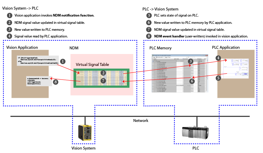
The sequence of events shown in the preceding figure is simplified; in practice, communication tasks are implemented with a series of signal changes.