Polar Coordinate Transformation Overview
Cartesian coordinates are a natural choice for the digital representation of images: digital cameras are made of a rectangular grid of light-sensors, which maps well to the two-dimensional array in software. The pixels are square, and position is specified by horizontal distance (x) and vertical distance (y).
Polar coordinates, on the other hand, are based on a circular grid. The pixels look like wedges or keystones, and position is specified by radius (r) and angle-from-horizontal (q). Thus, pixels are not uniform: as the distance from the origin increases, the pixels increase in area and change in shape.
The figure below compares the Cartesian and polar coordinate systems.
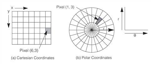
Comparison between Cartesian and polar coordinates.
You specify the resolution in both the radial and circumferential directions. In the above example, the radius represents the y-coordinate and is measured vertically in the positive direction; however, it can also be measured in the negative direction.

In the example, theta represents the x-coordinate and is measured in the positive direction; however, it can also be measured in the negative direction.

See also the class reference pages for ccEllipseAnnulusSection, Selecting the Polar Image Area.
If the resolution is too coarse (too few pixels, compared with the source image), the polar coordinate tool will only sample a subset of the source pixels. If the resolution is too fine (too many pixels), the tool will interpolate new pixel values. In both cases there is the danger of creating false information. See Selecting the Polar Image Area for more information.