Overview
The Cognex Vision Library allows you to display live and acquired images. The basic steps to display images are:
- Create a display object.
- Set the display object’s attributes.
- Display the image.
- Release the display object.
The example that follows shows these steps for a Cognex MVS-8100M frame grabber running under Windows and using a ccDisplayConsole window.
#include <ch_cvl/vp8100.h>
#include <ch_cvl/acq.h>
#include <ch_cvl/vidfmt.h>
#include <ch_cvl/windisp.h>
#include <ch_cvl/xform.h>
int cfSampleMain(int, TCHAR** const)
{
// Find the frame grabber
cc8100m& fg = cc8100m::get(0);
const ccStdVideoFormat& fmt =
ccStdVideoFormat::getFormat(cmT("Sony XC-ST50 640x480"));
ccAcqFifoPtrh fifo = fmt.newAcqFifoEx(fg);
// Step 1: Create a display console
ccDisplayConsole *display;
display = new ccDisplayConsole(cmT("Display Console"),
ccIPair(20,20), ccIPair(480,360));
// Step 2: Set the display console’s attributes
display->mag(-2);
display->closeAction(ccDisplayConsole::eCloseDisabled);
// The next three settings are the defaults
display->showToolBar(true);
display->showScrollBar(true, true);
display->showStatusBar(true);
// Use the Status Bar Text for any text you choose
display->statusBarText(cmT("Ready"));
// Start an acquisition
fifo->start();
// Get the acquired image
ccAcqImagePtrh img = fifo->completeAcq(
ccAcqFifo::CompleteArgs().acquireInfo(&info));
if (!img.isBound())
{
MessageBox(NULL, cmT("Acquisition failed"),
cmT("Display Error"), MB_OK);
return 0;
}
// Set the transformation object
// In this example, 40 image units (pels)
// map to 1 client coordinate unit
cc2Xform xform(cc2Vect(0,0), ccRadian(0), ccRadian(0),
40.0, 40.0);
// Step 3: Display the image
display->image(img, &xform);
// Draw some graphics into the image layer
ccUITablet tablet;
ccPoint where(2,2);
tablet.drawPointIcon(where, ccColor::red);
tablet.draw(cmT("Point (2,2)"), where, ccColor::blue,
ccColor::yellow, ccUIFormat());
display->drawSketch(tablet.sketch(),
ccDisplay::eDisplayCoords);
display->drawSketch(tablet.sketch(), ccDisplay::eImageCoords);
display->drawSketch(tablet.sketch(), ccDisplay::eClientCoords);
// Display message box to pause application
MessageBox(NULL, cmT("Display complete"),
cmT("Display Sample"), MB_OK);
// Step 4: Release display object
fifo = ccAcqFifoPtrh(0); // delete the fifo...
delete display; // ... before the display
return 0;
}
This example produces the display show in the figure below.
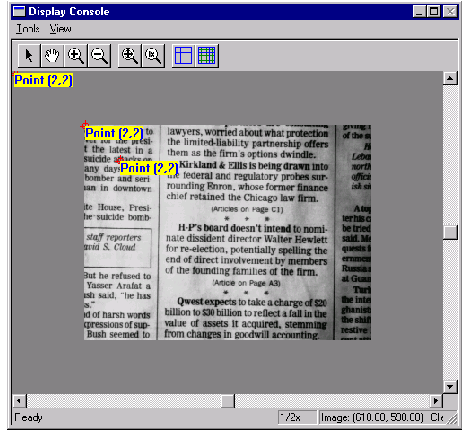
The example creates a point icon and a label at the same location (2,2). The location specifies the upper left-hand corner of the label. The point icon at 2,2 is small and difficult to see in this figure. The example then displays the point icon and the label using three different coordinate systems to illustrate their differences. eDisplayCoords displays the pair at location 2,2 of the display window. eImageCoords displays the pair at location 2,2 of the image. eClientCoords displays the pair at location 80,80 of the image because in our example, one client unit is equal to 40 pixels for both x and y. (Note that the label size is not scaled by the client coordinate transform).