AOI Setup
After the AOI features are extracted, users can set up the inspection items on the AOI Setup page located under "Alignment" category in Setup mode of the application.
This page allows users to configure measurements between pairs of AOI features, and set tolerances for every measurement results to check whether they are within required specs.
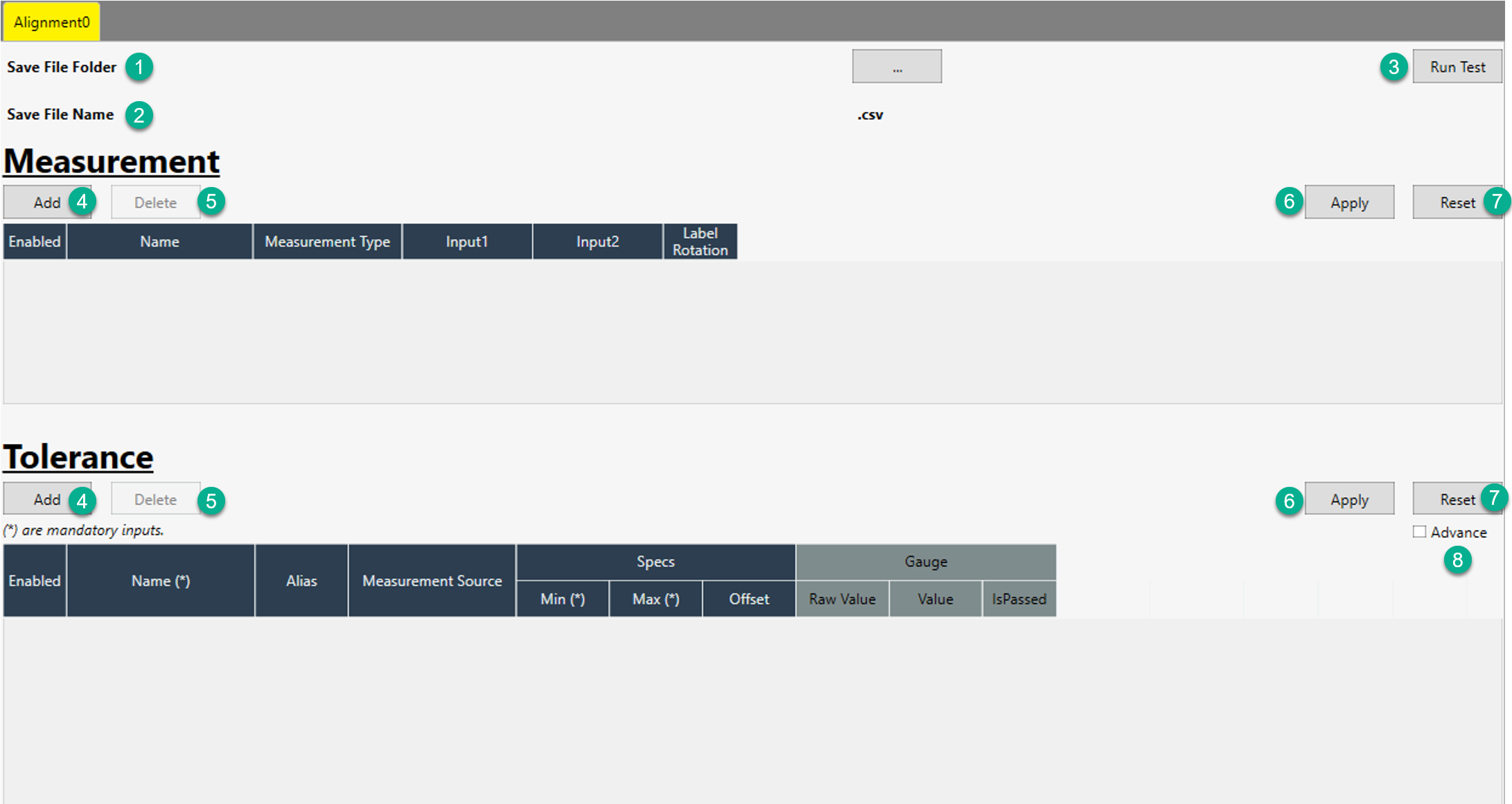
The indexed items on the screenshot above are described in the table below.
|
Index |
Items | Description |
|---|---|---|
| 1 | Save File Folder | The folder where to save inspection result log files |
| 2 | Save File Name | The name of the current inspection result log file |
| 3 | Run Test | To trigger the inspection task to load AOI features and run the inspection |
| 4 | Add | Add a measurement item or a tolerance check |
| 5 | Delete | Delete a measurement item or a tolerance check |
| 6 | Apply | Apply the changes to the measurement or tolerance configuration |
| 7 | Reset | Revert changes back to previous saved configuration of measurement or tolerance setting |
| 8 | Advance | Enable/Disable advanced options for tolerance setting |
Measurement
Each measurement item has the following columns need to be configured:
| Column | Description |
|---|---|
| Enabled | Enable/disable a measurement |
| Name | The name of the measurement item |
| Measurement Type |
By default it supports the three types: PointLine, PointPoint, SegmentSegment
However, user can customize other measurement types and their inputs and outputs, and make them available here for measurement options. See more information in Customize Measurement Types. |
| Input1 | The first feature input. Will be displayed in red if the feature is not found |
| Input2 | The second feature input. Will be displayed in red if the feature is not found |
| Label Rotation | The display angle of the measurement result label on image display. Default value is 0. |
In the example below, P1 and P2 are two corner points extracted, L1, L2, and L3 are three line segments extracted. And the measurement requirements are distances from: P1 to P2, L1 to L2, and P2 to L3.
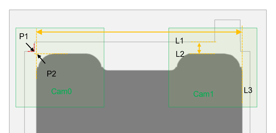
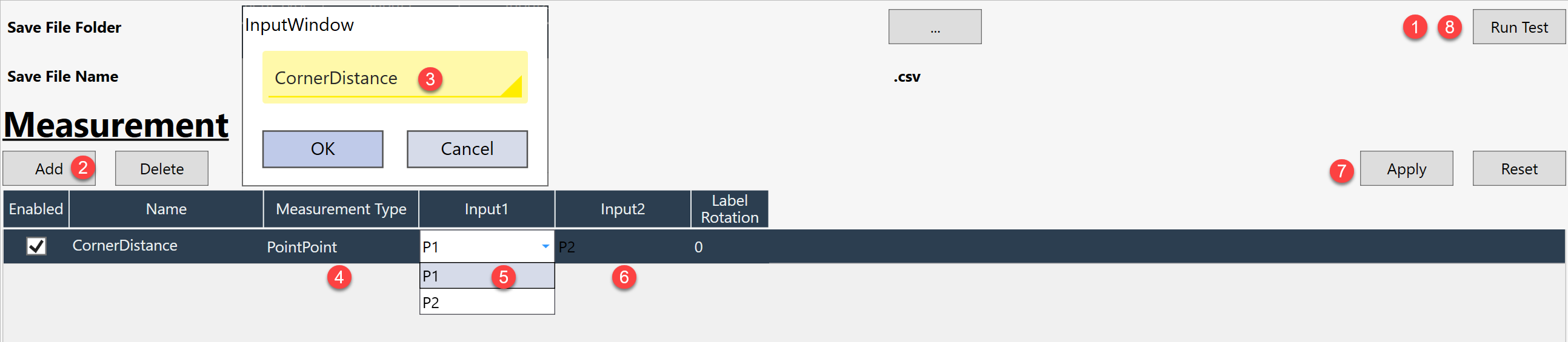
Here are steps to add the first measurement item (P1 to P2):
-
Click "RunTest" button at the upper right corner of this page to let the inspection task load the corresponding AOI features
-
Click "Add" button under Measurement category
-
Input the name of the measurement item in the pop-up dialog (such as "CornerDistance"), and click "OK" to confirm
-
Change the measurement type to PointPoint
-
Select P1 from the point feature list of Input1
-
Select P2 from the list of Input2
-
Click "Apply" button at the upper right corner of the Measurement category
-
Click "RunTest" button again to update the measurement result.
For L1 to L2, P2 to L3 measurements, the steps are the same except for the different measurement types and their corresponding input elements. Below is the result after all three measurement items were added:

Tolerance
A tolerance check setting has two modes for users to choose depending on their requirements for offset setting: simple mode and advanced mode.
Simple Mode
In simple mode, each tolerance check has the following columns to be configured:
| Column | Description |
|---|---|
| Enabled | Enable/disable a tolerance check |
| Name | The name of the current tolerance check |
| Alias |
The alias of the tolerance check which will be displayed on the result panel of the Home page and the corresponding image display. If it is not given, the Alias is the same with the Name. |
| Measurement Source | Select the source of value which needs to be checked from all available results of measured items |
| Min | Lower limit of the tolerance |
| Max | Upper limit of the tolerance |
| Offset |
Offset to the raw value of the selected Measurement Source |
| Raw Value | The value of the selected Measurement Source |
| Value | Corrected value, equal to Factor*Raw Value + Offset (Factor is hidden in Advanced Options with the default value of 1) |
| IsPassed |
True: Min ≤ Value ≤ Max False: Value < Min or Value >Max |
To check whether the three measured items above are within specs, the user can add tolerance checks for every items.
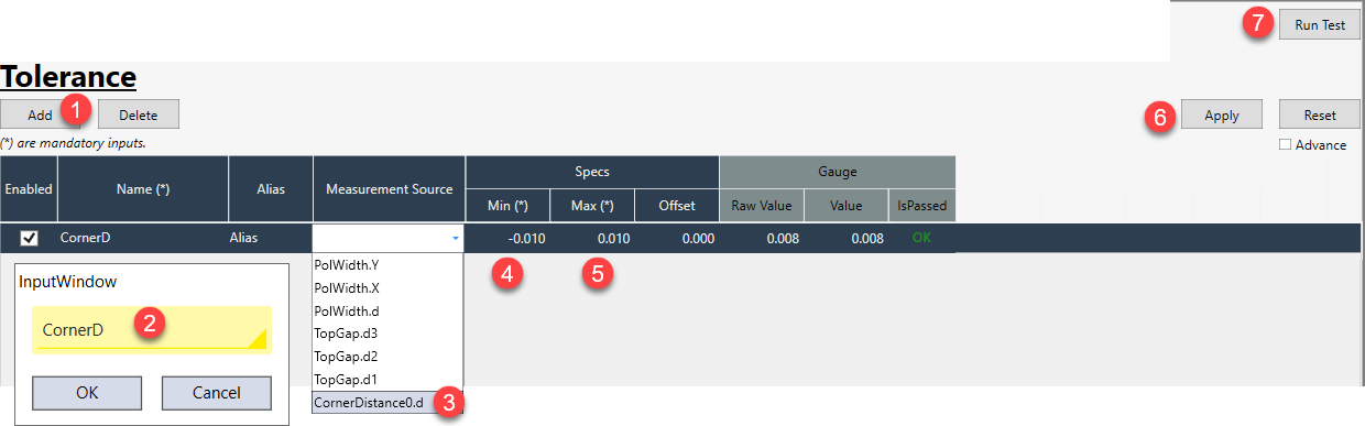
Take the CornerDistance for example, here are the steps to add a tolerance check for its result:
-
Click "Add" button to add a tolerance check
-
Input the name of the tolerance check (such as "CornerD") and click "OK" button to confirm
-
Select the corresponding measurement item's specific value, here is "CornerDistance.d"
-
Input the lower limit of the spec
-
Input the upper limit of the spec
-
Click "Apply" button to apply changes to the tolerance configuration
-
Click "Run Test" button to run the inspection task and check the result.
Here are the test results of the three added tolerance checks:

Advanced Mode
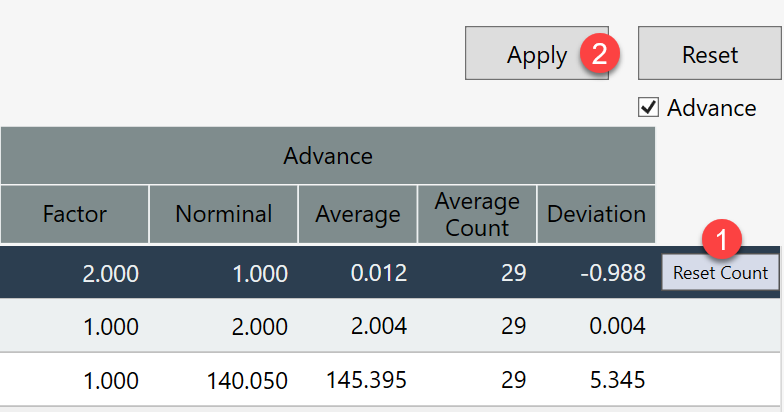
Advanced mode provides more information for users to compare the difference between an item's measured average value and its nominal, and then decide on how to adjust the offset and factor to narrow down the difference. If a user does not need the reference information to fine-tune offsets, he/she then can hide the advanced options by checking off the "Advance" check box at the upper right corner of the Tolerance category.
| Items | Description |
|---|---|
| Factor | Scale to the raw value |
| Nominal | The nominal of the selected Measurement Source specified by part design |
| Average |
The average value of accumulated corrected values (corrected values = Factor * Raw Value + Offset) |
| Average Count | The number of the accumulated corrected values which were used for averaging |
| Deviation | Deviation = Average - Nominal |
In the example below, the averages are calculated based on 29 corrected values. If a user wants to recalculate the average based only on new data, he can first select that tolerance check; second, click the "Reset Count" button at the end of the selected line; third, click "Apply" button to confirm; fourth, run inspection again by clicking "Run Test" button or sending inspection commands to the vision system. Then the average value will be recalculated based on newly accumulated data.
Results
The run time inspection results will be listed on result panel on the Home page of the application such as below. If a value does not pass a tolerance check, that value will be displayed in red, otherwise in black.
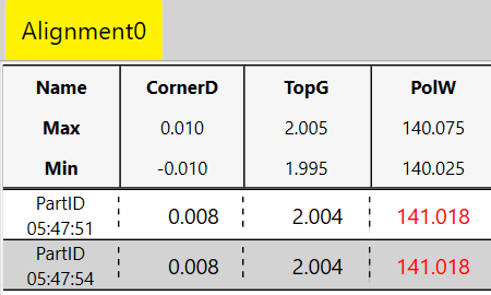
To customize how many lines of history data to display on the result panel, users can open AlignmentSystem_AutoModePage in edit mode, select the MeasurementHistoryControl on the page, and change its Maximum Item property to the desired value.

The measurement result graphics will also be displayed on the corresponding image displays. When a tolerance check is passed, the graphics will be displayed in green, otherwise in red.
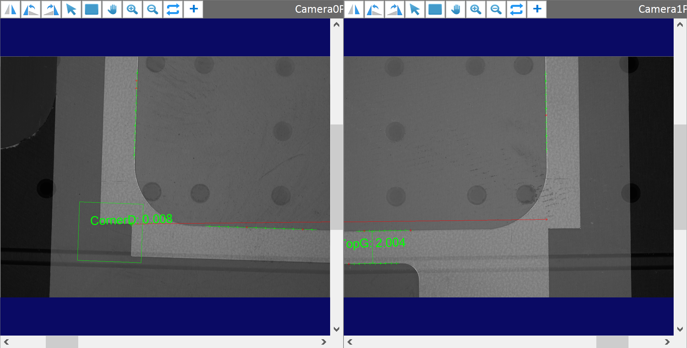
To view the measurement result between two cameras, users can right click "Fit Images and Graphics" on one image display, then the measurement result label will show up in the middle of its two input features.

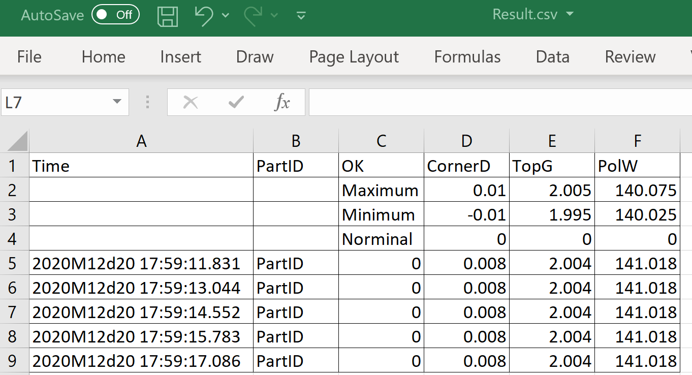
If a user has already configured the result log file name and its path, then after running inspection task for at least one time, the measurement data and their tolerance settings can be found in the saved log file.