Alignments
Alignment component allows users to configure the techniques for alignment, assembly, or inspection computation. One alignment in Configuration Wizard has one alignment task in the corresponding auto-generated project.
Add
Click Add Alignment to add an alignment component in the wizard workspace.
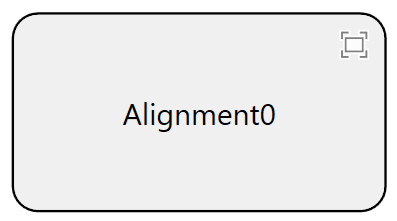
To change the name of it, double-click Alignment0 to edit it.
Connect
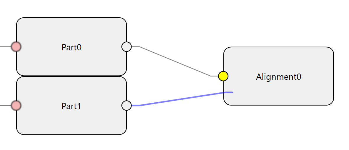
Alignment needs to be connected to at least one part component before it can be configured. For alignment applications, this component only needs to connect to one part. For assembly applications, it should connect to the two parts that will be assembled together afterward. For inspection applications, this component can connect to one or two parts as long as these parts' AOI features share the same coordinate space and with different feature names.
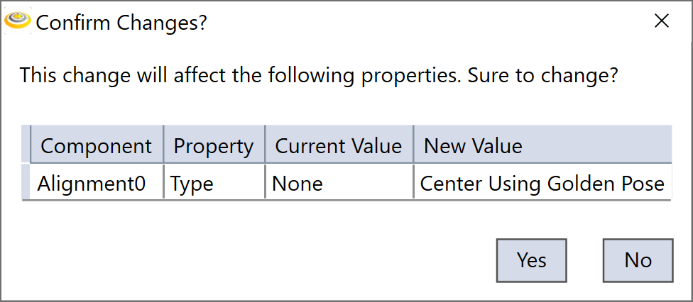
When the component connects to the first part, by default the wizard will set its type as "Center Using Golden Pose"; click "Yes" in the pop-up dialog to continue.
However, if the type of the finder connected to the part on the left is Multiple Parts or AOI, then the type of alignment component that connects the same part on the right side will be set as "Multiple Parts" or "AOI" respectively.
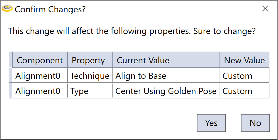
When the alignment component connects to the second part, the wizard will change its type to "Custom" for assembly applications; click "Yes" in the pop-up dialog to continue, you can change the type afterward. If it is inspection applications, then the alignment component type will stay as "AOI".
There could be cases when you try to connect the second part to an alignment component, but the component does not accept:
There are two causes of this phenomena:
-
The two parts are configured as on the same station for an assembly application
In assembly applications, the two parts to be assembled should be on different stations. To solve it, check and reconfigure the motion devices in both parts, make sure the two devices are different, then reconnect them to the alignment component.
-
The feature finder type is not compatible with alignment type
The AOI alignment component can only accept parts connected to AOI finders, change the corresponding finder types to "AOI features" to continue the connection.
Set
Open the alignment dialog box, configure the following parameters according to the real application.
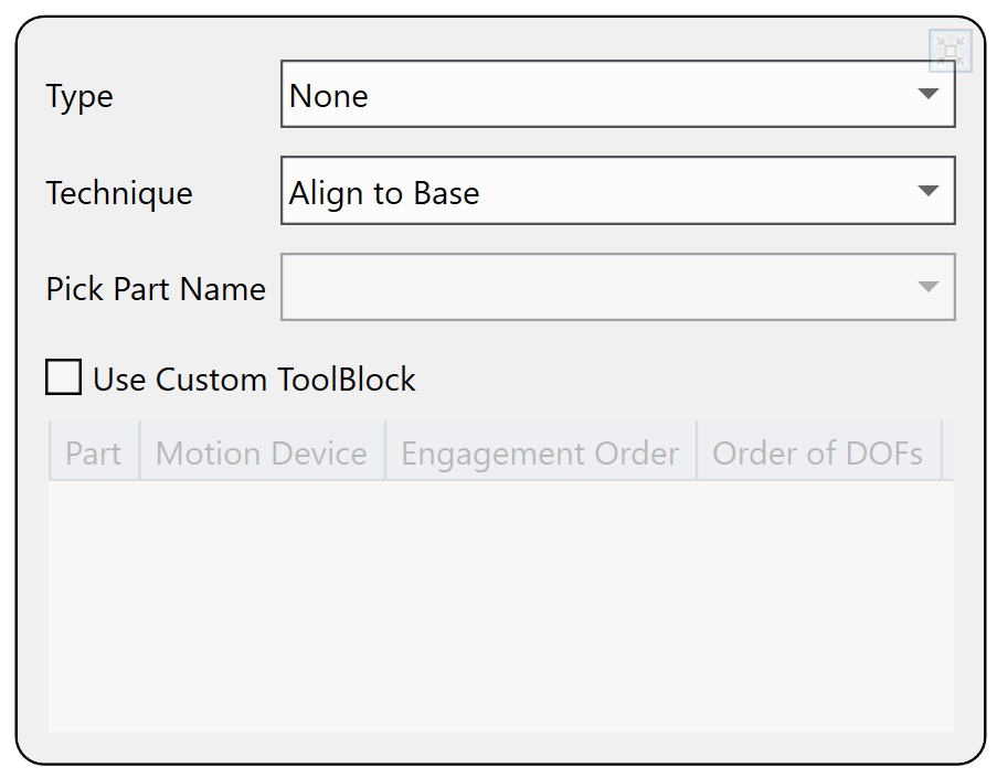
Type
| Option | Description |
|---|---|
| Custom | Select this option to create an empty PoseComputer subtask inside the corresponding alignment task in the generated project. Users can customize this subtask, and when the Configuration Wizard reruns, the user customized contents in this PoseComputer subtask will be maintained. |
| None | Select this option when an alignment component has no input connections. |
| Center Using Golden Pose |
This option can be used either for one part alignment application or two parts assembly application in which each part aligns to its target pose defined during train time. For more information, please refer to Alignment Procedure and Assembly Procedure Using Golden Pose |
| Center Using Paired Features |
Select this option to align parts using one part's features as the target features pose for another part. For more information, please refer to Assembly Procedure Using Paired Features. |
| Multiple Parts | Select this option to align multiple parts to one common target pose. |
| AOI | Select this option to run inspection (such as measurement, gauging) based on extracted AOI features. AOI function allows users to get features from different feature finders that share the same coordinate space, however, the feature names should be manually modified as unique among all feature finders. |
Technique
| Option | Description |
|---|---|
| Custom |
Select this option to keep the PoseComputer subtask empty. Users can customize this subtask, and when the Configuration Wizard reruns, the customized content in PoseComputer subtask will be maintained. |
| Align To Gripper |
Select this option when a part placed on a stationary platform needs to be picked up by a gripper. The gripper will first adjust its own position based on the vision system's feedback, then pick the part up at a fixed relative pose to the part. For more information, please refer to Align to Gripper |
| Align To Base | Select this option when a part is attached to a motion device (such as a stage) to be aligned. After alignment pose computation, the part is moved by the motion device to the part's trained golden pose. For more information, please refer to Align to Base |
| Assembly Blind Transfer |
Select this option when the two parts are handled in this way: the first part is placed on and moved by a motion device at the feedback of the vision system to the expected relative pose of the second part; one part is blindly transferred to the other part's side, and the two parts are assembled. For more information, please refer to Assembly Blind Transfer |
| Assembly Guided Pick |
Select this option when the two parts are handled in this way: the picking device such as robot or gripper adjusts its own position first before picking up the first part based on the vision system's guidance; the picking device picks the first part up and moves it over to the second part where the two parts are assemble together. For more information, please refer to Assembly Guided Pick |
| Assembly Guided Place |
Select this option when the two parts are handled in this way: the picking device such as robot or gripper blindly picks up the first part and then adjusts its pose together with the part to fit the first part to the second part's pose based on the vision system's guidance; the picking device moves the first part over to the second part's side, and the two parts are assembled together. For more information, please refer to Assembly Guided Place |
| Split Axis | Select this option when three elements of moving freedom(X/Y/Theta) are split to 2 or 3 different stages in machine. |
| Measurement | Select this option to run measurement in alignment task. |
Pick Part Name
The name of the part whose pose will be adjusted by a motion device during alignment/assembly process. It is automatically selected by the wizard based on user's configuration.
Use Custom Tool Block
Select this check box to have the run-time application present a VisionPro tool block edit control that you can use to implement the alignment/assembly pose computation.
Delete
Select the alignment component, and hit "Delete" button on the keyboard.