AOI Feature Extraction
Feature extraction is the prerequisite to run inspection. AlignPlus4.3 inspection function supports measurements between pairs of following feature types:
-
CogLineSegment
A CogLineSegment object can indicate the location of an edge on a part. It is often used to measure gaps between two edges or distances between points and edges. A CogLineSegment feature can be output by an AOI Features Finder (equal to Generic Features Finder) using a CogFindLineTool/CogCaliperTool/CogFindCornerTool inside the finder.
-
CogTransform2DLinear
A CogTransform2DLinear object can indicate a part's x, y, theta (specified by properties: TranslationX, TranslationY, and Rotation respectively) in selected space; if the theta element is not useful for measurement, CogTransform2DLinear can also be used as a point containing x and y values in its TranslationX and TranslationY properties. A CogTransform2DLinear object can be one output of an AOI Features Finder using a CogPMAlignTool/other tools inside the finder.
Example of AOI Feature Extraction
The example below shows how to extract AOI features using an AOI Features Finder.
In the assembled part shown below, the following items needs to be measured:
-
Corner Distance: distance between P1 (corner point of transparent adhesive film) and P2 (corner point of dark polarizer)
-
Top Gap: distance between L1 (top line of the film) and L2 (top line of the polarizer)
-
Width of polarizer: distance between P2 (corner point of dark polarizer) and L3 (right line of polarizer)
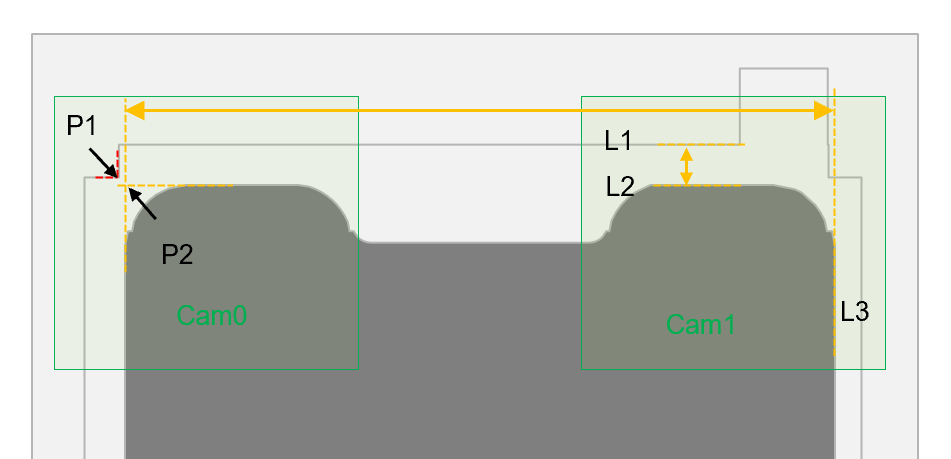
In the vision system, two cameras are looking at each corner of the assembled part. For Cam0, two point needs to be extracted: P1 and P2. For Cam1, three line segments need to be extracted. In the Configuration Wizard, "AOI Features" type should be selected in the finder component, so that after the application is generated, both points and lines can be extracted from one features finder.
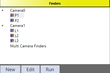
After calibration, the user can start configuring the features finder on HMI. Here is an example how the features finder should be configured inside: two custom feature finders under Camera0 are added to find two corner points (P1 and P2), three custom feature finders under Camera1 are added to find three edges of the assembled part (L1, L2, and L3).
Feature Extraction under the first Camera
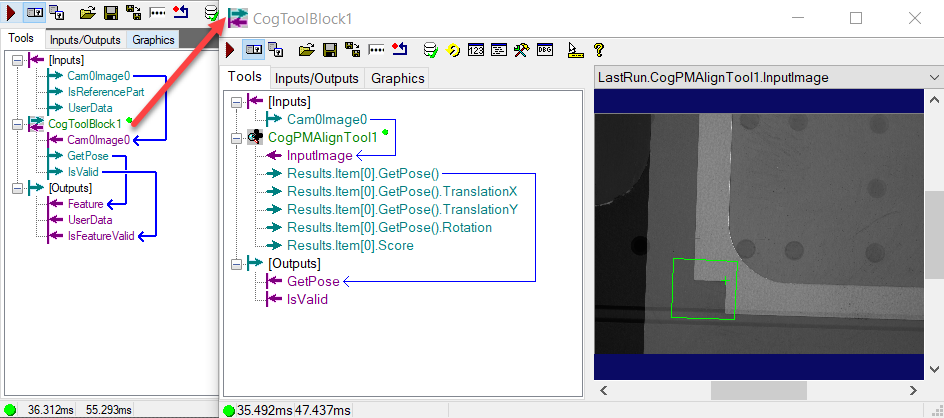
For P1, the user can either choose CogPMAlignTool or CogFindCornerTool to find the corner point of the film within the custom toolblock. In the example below, CogPMAlignTool is used and its GetPose() output is directly passed down as the feature output of current feature finder.
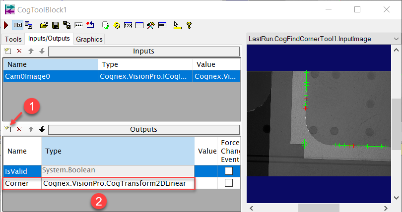
For P2, here CogFindCornerTool is used to find the corner point of the polarizer within the custom toolblock. However, since CogFindCornerTool does not have output of a CogTransform2DLinear object, the user needs to add a CogTransform2DLinear type of output manually to current custom tool block and give the corner's x, y values to this ouput's TranslationX and TranslationY properites via scripting.
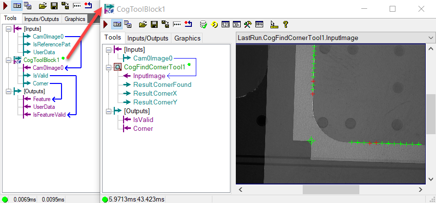
A CogTransform2DLinear type can be found under "Cognex.VisionPro" namespace from Cognex.VisionPro.Core.dll.
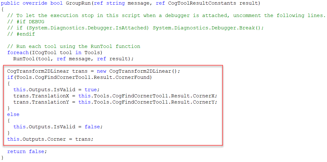
The script below created a new CogTransform2DLinear object first, then assigned the CornerX and CornerY ouputs of the CogFinderTool to the object's TranslationX and TranslationY properites, and at last assign the object to the current toolblock's output.
Feature Extraction under the second Camera
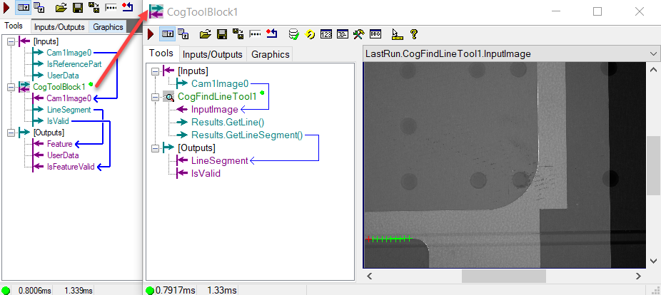
For the three line segments extraction, one can use a CogFindLineTool within each custom toolblock finder to find the desired edge and assign its line segment output as the output feature of that finder.
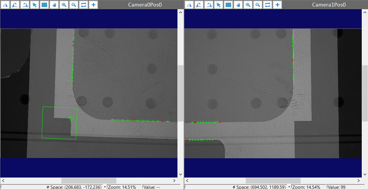
Result
The AOI features extraction results on run time images are shown as below in the image display.