Offset Compensation
In alignment applications, run time part is aligned to its trained golden pose. However, the trained golden pose may not be at the ideal pose for further mechanical operation such as dispensing, gluing. Therefore, even run time part is perfectly aligned to its golden pose, the constant discrepancy between golden pose and the ideal target pose caused by mechanical positioning should be compensated to achieve alignment goals.
Likewise, in assembly applications, even if features from both parts are precisely located, and motion device moves accurately to target pose provided by the vision system, the gaps between them may not meet the specifications when the two parts are actually assembled. These differences between actual gaps and ideal gaps are caused by other mechanical process such as part transferring, or attachment. However, these differences are typically constant so that they can be compensated.
Offset compensation function allows user to manually add offset values to run time part features, so that when motion device moves to target pose provided by vision system, the desired alignment or assembly characteristics can be obtained. It currently only support point features.
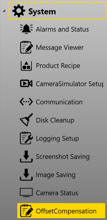
Offset compensation function can be found under System category in setup mode.
It provides three methods of compensation: XYTheta mode which compensates part feature locations based on X, Y, Theta offsets, XXY or XYY mode which compensates based on three gaps measured between real part and its target position.
XYTheta Mode
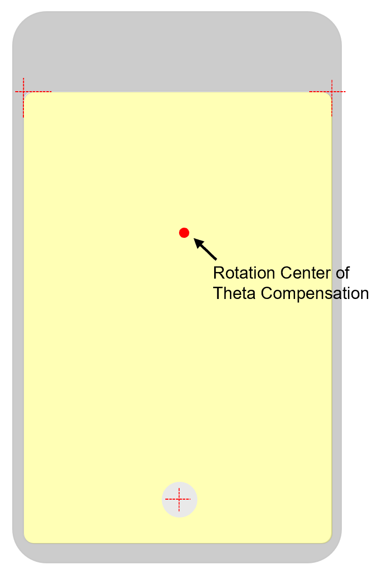
In XYTheta mode, x offset is offset along stage's x axis, y offset is offset along stage's y axis, theta offset(Ө)'s direction is from stage's x axis to its y axis. Those offsets could be calculated based on inspection results from inspection machine or calculated by operator to bring run time part to its target pose. After receiving these offsets, this function will first apply the theta offset by rotating all features around features' mean center. Second, compute all features' location changes caused by theta offset. Third, add the x, y offsets to features' changed locations computed in the second step.
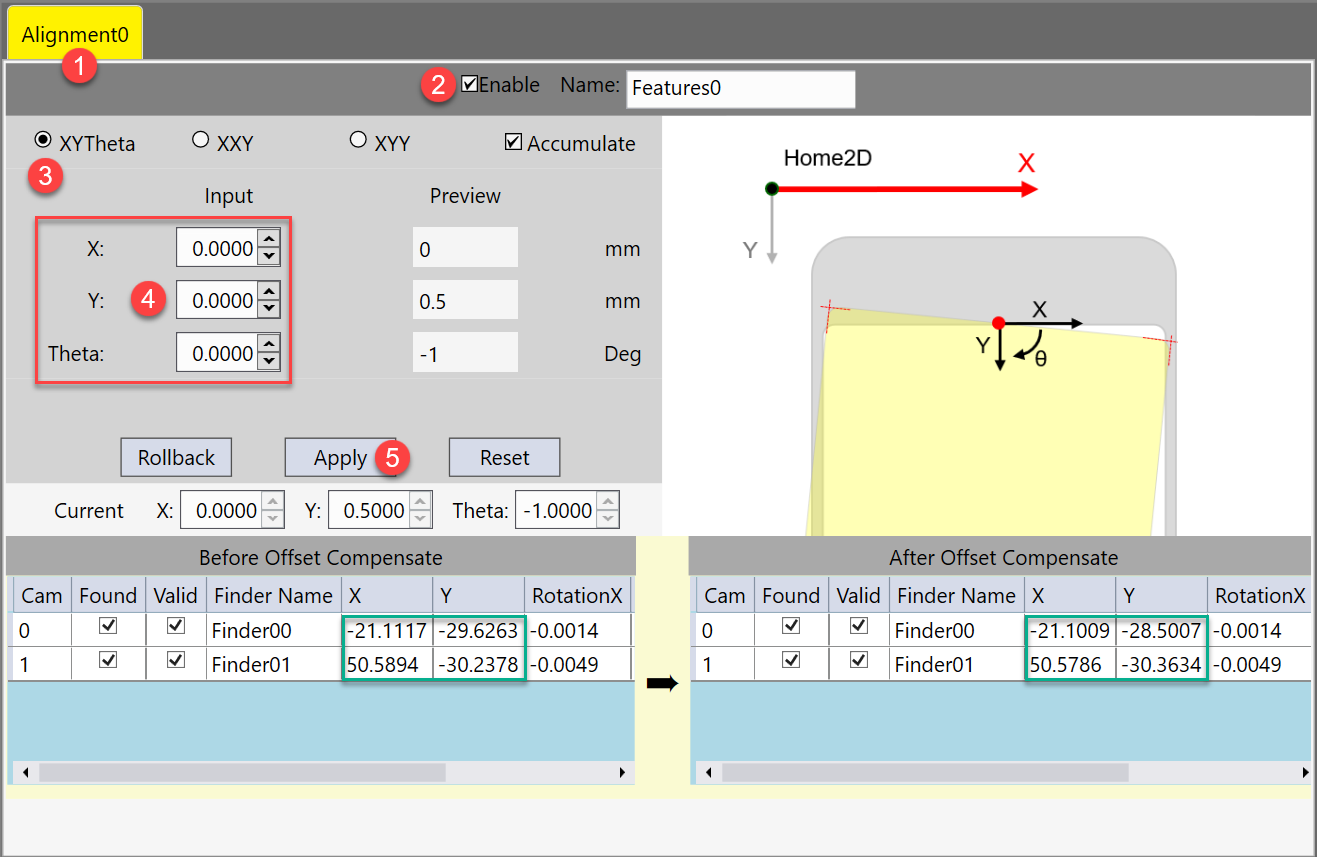
Here are the steps to add x, y, theta offsets:
- Select one station
- Enable that station's compensation function
- Choose XYTheta mode
-
Input manually estimated X, Y, Theta offsets.
X, Y, Theta offsets should be based on current part coordinate. Theta is in degree.
- Run feature finding and pose computer one time.
-
Click Apply button to apply the offsets.
After applying, one can find the current part's feature coordinates before and after compensation.
- Save current recipe so that these offsets will be saved in the alignment sub recipe.
After the offsets are applied, you may find alignment or assembly result improved, but still a bit away from specifications. In this case you may want to add some extra small offsets to the current ones. This can be done checking on Accumulate.
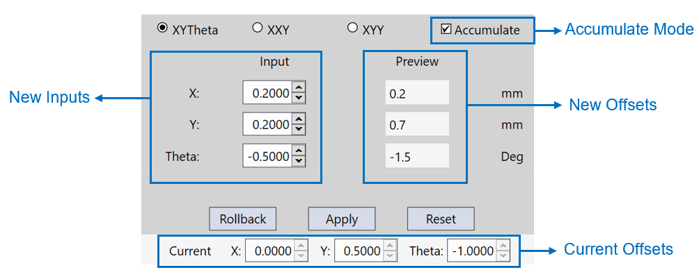
As marked above, New offsets = New Inputs + Current Offsets. Click Apply button to overwrite current offsets with new offsets.
If by chance the newly added offsets make result drift further away, you can revert to the last offsets by clicking Rollback button, or clear all offsets by clicking Reset button.
Compensate Based on Gaps
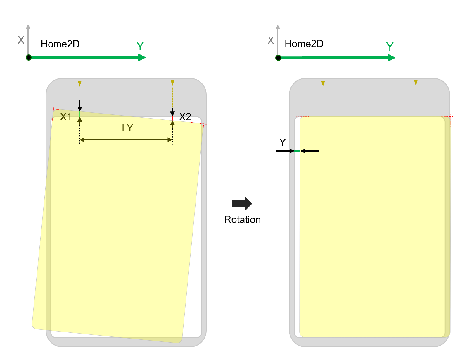
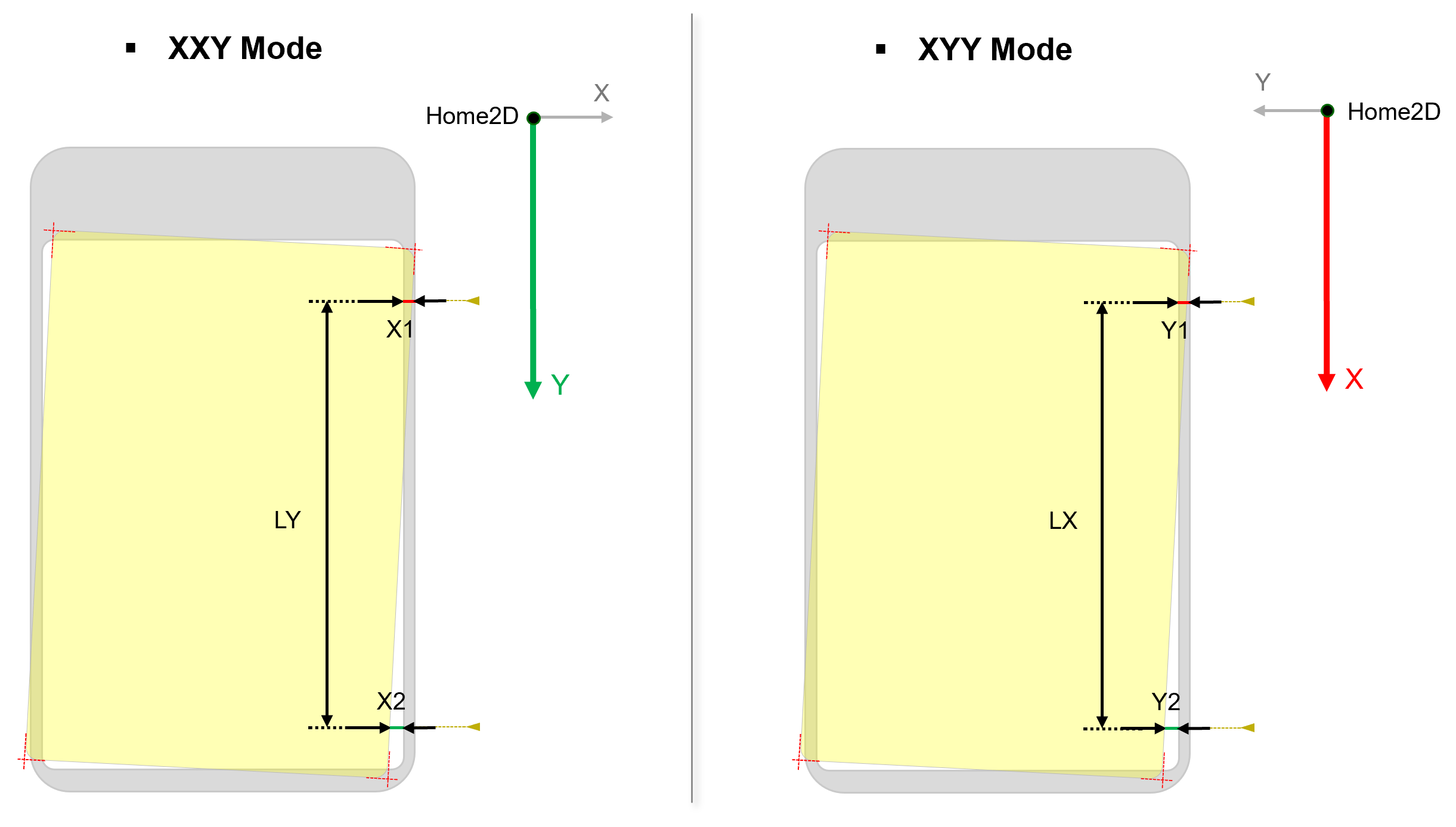
Another way to compensate theta of run time part is by inputting two symmetric gaps between run time features locations and their corresponding target locations along one side of the part. If the gaps are equal, it indicates no theta compensation. Otherwise, an angle should be computed based on the two gaps' difference and the distance between where the two gaps are measured, and then compensated it back. When this side of part is along y axis of the stage, please choose XXY Mode. Otherwise, choose XYY Mode.
XXY Mode
XXY Mode uses two gaps along x axis of the stage, one gap along y axis of the stage to compensate run time part feature locations.
| Item | Data Type | Description |
|---|---|---|
| X1 | Signed Double |
First measurement point's x gap from its target position, or how much the first point should move along x axis to its target x position. Note: The first measurement point is the point which is closer to stage's origin compared with the second point
|
| X2 | Signed Double |
Second measurement point's x gap from its target position, or how much the second point should move along x axis to its target x position. Note: The second measurement point is symmetric to the first point on the part and is farther away from stage's origin
|
| Y | Signed Double | The estimated Y offset of run time part after its theta has been compensated |
| LY | Unsigned Double | Absolute value of Y direction difference between two points where X1 and X2 are measured |
The steps of adding XXY offsets are the same as those of adding XYTheta offsets. Only the inputs have been changed to X1, X2, Y, and LY.
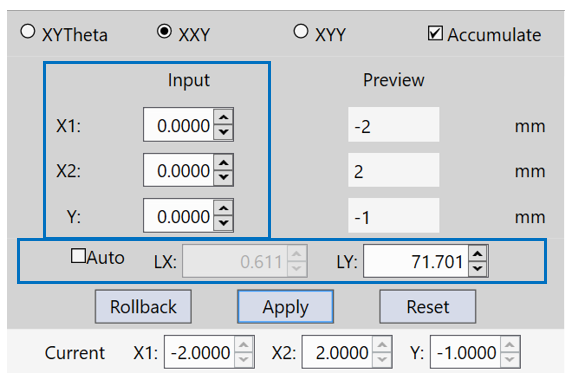
LY can either been manually inputted or automatically calculated by offset compensation function based on found run time feature locations. Check on "Auto" to let the program calculate LY and LX(x difference between two measurement points, should be 0 when there is no rotation issue, for reference only) automatically. The auto-calculated LY may be slightly different with the y direction distance between two measurement points as the measurement points may not be feature points. However, their difference is negligible because the mechanism of offset compensation is to compensate the part to be one-step closer to its ideal pose each time for several times to avoid over-compensation.
After receiving these values, offset compensation will first compute theta offset based on X1, X2 and LY. Second, compute all features' translation(x, y) changes resulted from rotating the part by theta around all features' mean center. Third, compute x offset for each feature based on X1 or X2 depending on which side the feature is and its x changes caused by rotation. Fourth, compute a common y offset for all features based on input Y and average y changes of all features caused by rotation.
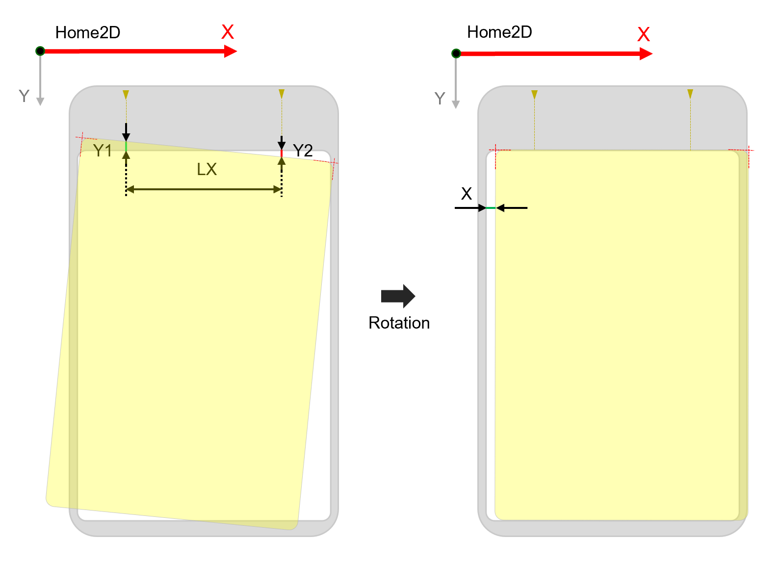
XYY Mode
XYY Mode uses one gap along x axis and two gaps along y axis of the stage to compensate run time part feature locations.
| Input | Data Type | Description |
|---|---|---|
| X | Signed Double | The estimated X offset of run time part after its theta has been compensated |
| Y1 | Signed Double |
First measurement point's y gap from its target position, that is to say, how much the first point should move along y axis to its target y position. Note: The first measurement point is the point which is closer to stage's origin compared with the second point
|
| Y2 | Signed Double |
Second measurement point's y gap from its target position, that is to say, how much the second point should move along y axis to its target y position. Note: The second measurement point is symmetric to the first point on the part and is farther away from stage's origin
|
| LX | Unsigned Double | Absolute value of Y direction difference between two points where Y1 and Y2 are measured |
The steps of adding XYY offsets are the same with adding XXY offsets. Only the inputs have been changed to Y1, Y2, X, and LX.
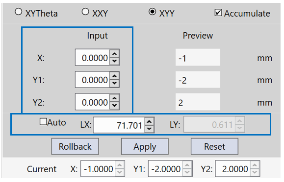
LX can also either be inputted manually or auto-calculated by this function using x difference of found feature locations. The way to compute run time feature location changes is the same with the XXY mode, only replacing X1, X2 with Y1, Y2, replacing LY with LX.
How to compensate multiple features
When there are more than 3 point features, it is recommended to measure the gaps along the long side of the part if XXY or XYY mode is used.
When "Auto" is checked on, offset compensation under XYY/XXY mode will use x/y difference between two features along the long side of the part as LX/LY.
However, if the mean center of all features is not expected to be rotation center of theta compensation, it is recommended to use XYTheta mode only.