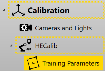
Hand-eye Calibration Training Parameters
Hand-eye calibration parameters influence the computation of the relationship between the camera and the motion device. It is used to provide the underlying tool information about the system being calibrated. The tool uses this information to generate valid and accurate result. Hand-eye calibration parameters setting is located under Calibration category.
Checkerboard Based Hand-eye Calibration
The following section describes the various hand-eye calibration parameters that can be adjusted when a checkerboard is used as a calibration target. It briefly describes how each parameter effects the computed calibration result.
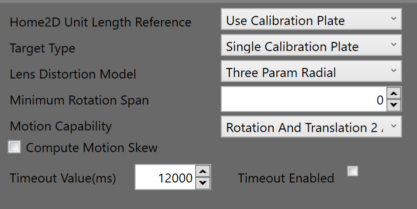
Home2D Unit Length Reference
-
Use Calibration Plate
Indicates that an accurate calibration target is being used and that the parameters of the calibration target can be assumed to be the ground truth during calibration. When an accurate calibration target is used, the relative positions of the cameras computed during hand-eye calibration is accurate.
-
Use Motion Stage
Indicates that the motion device is accurate. In this mode, the relative positions of the cameras are computed by the rotation of the motion device. If the rotation is inaccurate or not sufficient, the estimated positions of the cameras would be inaccurate and integrating data across cameras would become unreliable.
Target Type
-
Single Calibration Plate
Indicates that a single calibration target is being used to hand-eye calibrate the multiple cameras. Following calibration, all cameras would have the ability to map their features to a common Plate2D. The relative position of the cameras are estimated accurately. The absolute cameras positions in Home2D is influenced by the accuracy and extent of rotation during the hand-eye calibration process.
-
Separate Calibration Plates
Indicates that a separate calibration target is being used for each camera. In this mode, the checkerboard is used to compute lens and perspective distortions, but the motion device is used to compute the relative and absolute positions of each camera in Home2D. The accuracy of this computation depends upon the accuracy and extent of the rotation during the calibration process. The user should use this option only if a single calibration target cannot be used for the application.
Lens Distortion Mode
-
This model calibrates for nonlinear optical distortion and perspective distortion. When compared with PerspectiveAndRadialWarp, this mode adds additional coefficients that properly model the location of the optical center. This mode is recommended for lenses with minimal to moderate distortion, typically those with focal lengths greater than 6mm.
-
SineTanLaw Projection
This model calibrates for nonlinear optical distortion and perspective distortion. When compared with ThreeParamRadialWarp, this model uses a computation model that is appropriate for lenses with moderate to severe distortion, typically those with focal lengths less than 6mm.
-
No Distortion
This mode assumes that the relationship between pixels and Home2D is an affine transform. This mode does not compensate for lens or perspective distortion. One benefit of this mode is it reduces processing time of image correction significantly.
Minimum Rotation Span
This parameter is only available as a protection mechanism, to ensure that the user does not accidentally generate poses with a smaller rotation angle span. During the hand-eye calibration process if the rotation angle span is less than this value, there is no guarantee that the hand-eye calibration result would be accurate.
Motion Capability
Specify motion device's capabilities in moving calibration target.
| Options | Degree Of Freedom | ||
|---|---|---|---|
| X | Y | Theta | |
| Rotation And Translation 2 Axes | √ | √ | √ |
| Rotation Only | x | x | √ |
| Translation Only 1 Axis | √ | x | x |
| Translation Only 2 Axes | √ | √ | x |
| Rotation And Translation 1 Axis | √ | x | √ |
Compute Motion Skew
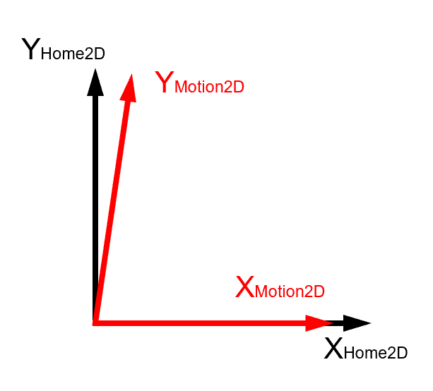
Enable or disable motion skew computation. Some lower accuracy motion stages may exhibit a skew between the X motion axis and Y motion axis as shown in the figure below. Hand-eye calibration can compute the skew and correct it in transforms between Home2D and the motion stage coordinate space. However, if there is not enough data to compute, the calculated results may deviate far away from motion's real parameters. To avoid that, it is recommended to disable motion skew computation when there are limited features to compute.
Timeout Enabled
Enable or disable timeout for calibration.
Timeout Value(ms)
The calibration time out value in milliseconds.
Part-based Hand-eye Calibration
Part-based hand-eye calibration parameters page has two significant user interfaces. The first, Calibration Parameters, is for setting the hand-eye calibration parameters. The second, is for setting up feature finders that track features on the part during the hand-eye calibration process.
![]()
Calibration Parameters
The calibration parameters for part-based hand-eye calibration are almost the same as checkerboard based hand-eye calibration. This section simply outlines differences:
-
Part-based hand-eye calibration does not have Home2D Unit Length Reference parameter. This is because the calibration process depends upon the accuracy of the motion stage to provide a length reference.
-
The Target Type parameter that is described below:
-
Tracked Part Dense Features
Used when the number of fiducial tracked during the hand-eye calibration process is more than three.
-
Tracked Part Sparse Features
Used when the number of fiducial marks is at-least one but less than three.
Compute Image Skew
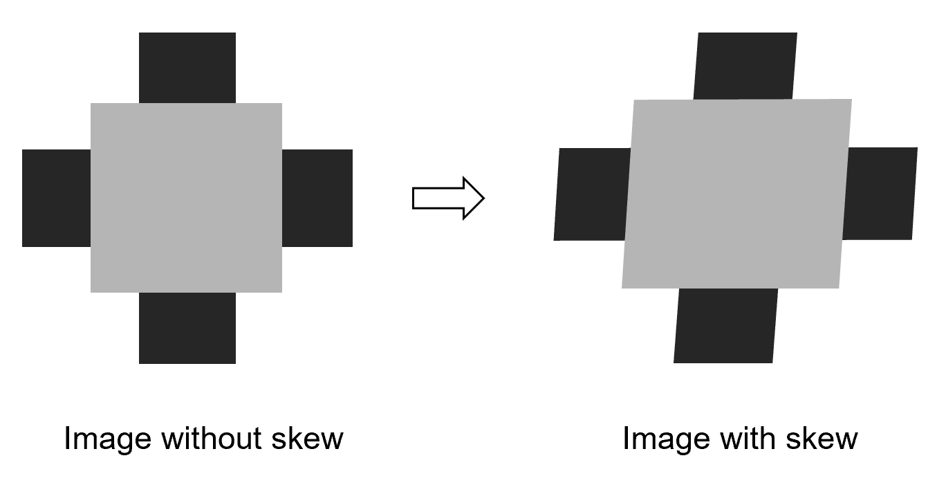
Enable or disable image skew computation. Image skew makes each pixel acquired on image drift away in y direction proportionately to its distance to the top or bottom line of the image. Image skew could cause accuracy problems for both feature locating and measurement, so it is better to get it corrected. However, when there are not enough features in part based calibration, enabling image skew computation may result in incorrect compute result. Therefore, it is recommended to disable it when features are sparse.
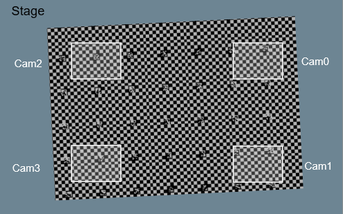
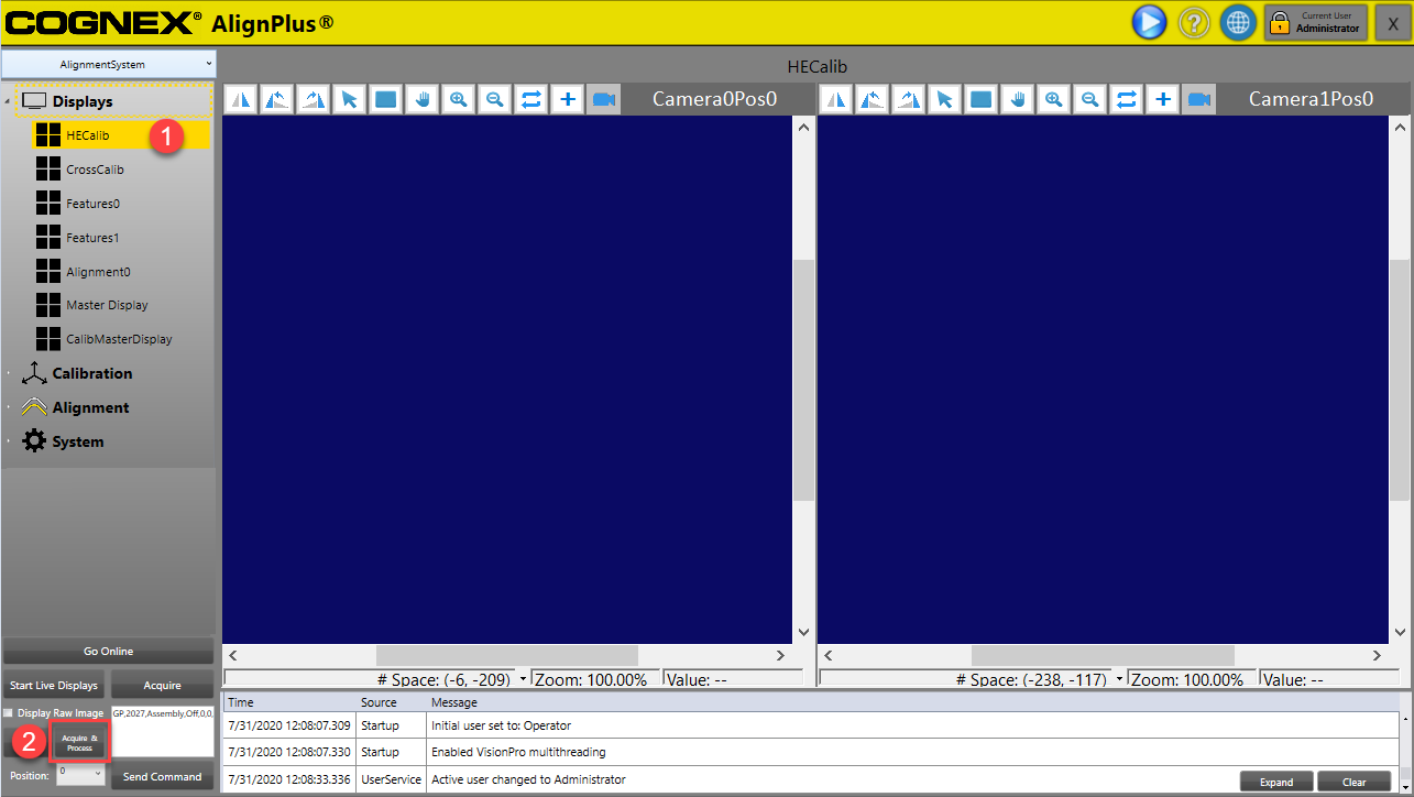
Feature Finding User Interface
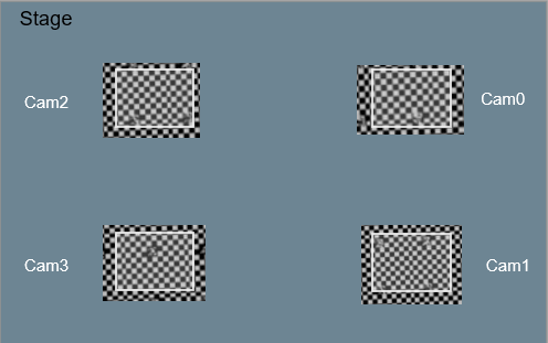
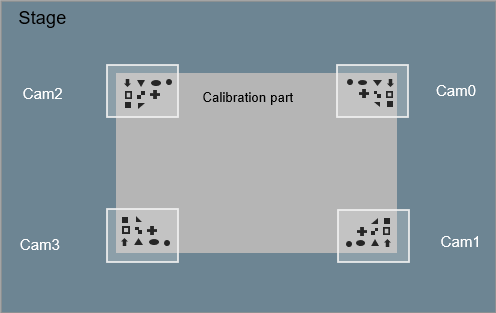
Feature Finding UI is a point features finder UI that is used to set feature finding vision tasks for part-based hand-eye calibration. Before start adding vision tools, the feature finding UI should first have images for each camera. To get those images, one can first select the related part-based hand-eye calibration display which is under Display category, and then click Acquire & Process button in function panel below.
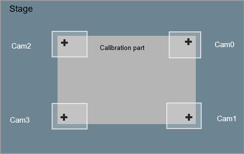
After the images have been acquired, the next step in the setup to be completed is in the training parameters page where feature finders should be added for part-based hand-eye calibration. Below is an example of tracking one fiducial mark using PatMax Finder.
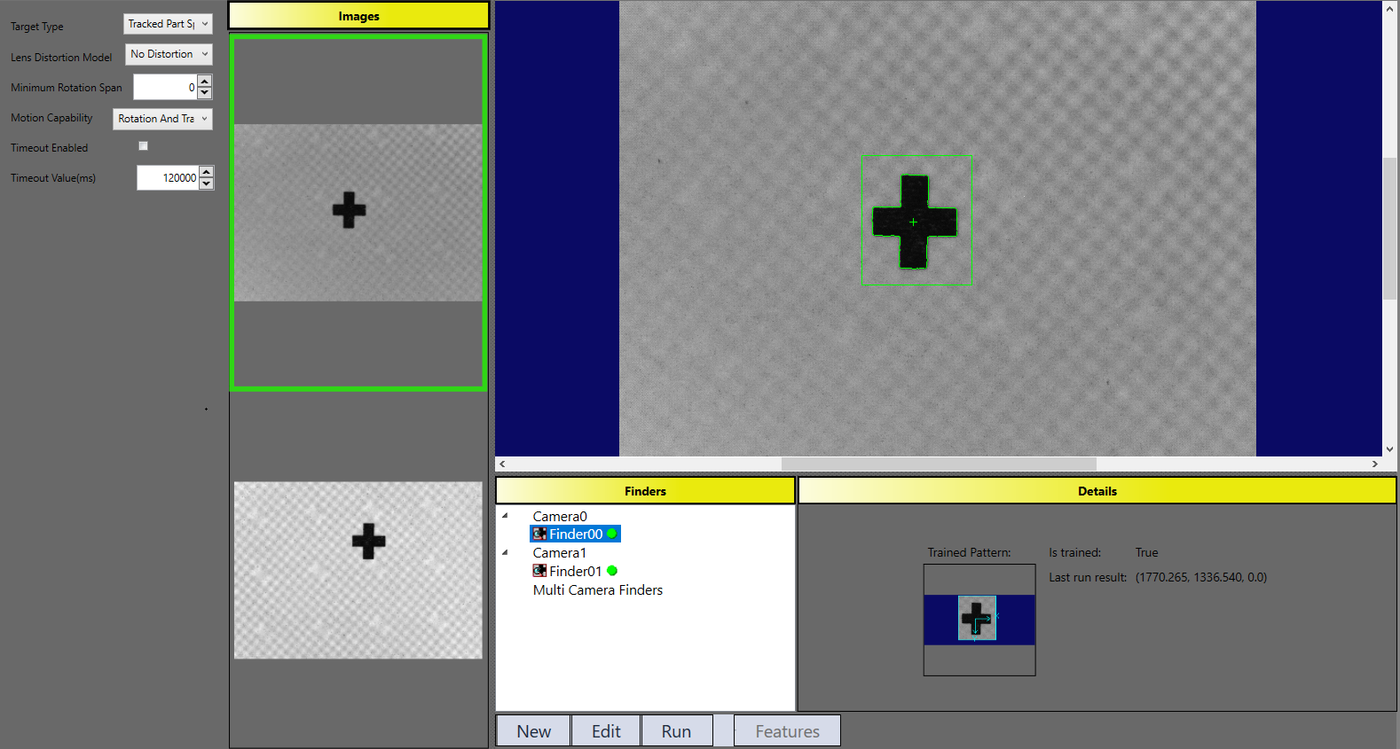
If there are more features to be tracked, you can add more feature finders under each camera. One thing to pay attention is that hand-eye calibration will track each feature through the whole hand-eye calibration process, accumulating its positions at every motion pose for final computation. So, during feature finder setting, make sure those features will be correctly and uniquely found under each FOV during hand-eye calibration process, and their output positions should always be within FOV.